Сделать основным языком

Решение EMC EMC EMC

Решение EMC EMC EMC

Our e-motor EMC testing solution are tailoring to meet the growing demands for compliance, performance testing across industries such as automotive, морской пехотинец, and aerospace. Therefore These solutions are both cost-effective and efficient, ensuring consistent and repeatable test results across a variety of setups and configurations.

We offer full vehicle test setups, which equips with multi-axle chassis load machines, four-wheel drive capabilities, fully automated remote antenna positioning, and specialized charging mode test configurations. This flexibility makes our solutions ideal for testing not only complete vehicles but also Electric or Electronic Sub-Assemblies (ESA), covering a wide range of applications.

One standout feature of our load machines is the conventional through-shaft EMC chamber installation, designed to meet the CISPR 25 standard. This installation is perfect for testing e-motors ranging from smaller 20 kW units found in motorcycles to larger 700 kW systems commonly used in commercial vehicles. It ensures a thorough evaluation of all dynamic e-motor requirements, helping to accurately assess performance characteristics.

Flexibility of the test bench

As situations where a permanent load machine installation isn’t feasible, we provide mobile testing equipment as a flexible alternative. This mobile setup can use in multi-purpose or existing EMC chambers, offering the same comprehensive capabilities and functionality as our stationary systems, though with a slightly limited power capacity range.

Moreover Our solutions are designed to ensure you can meet the highest standards of performance and compliance, all while maintaining flexibility and cost-efficiency for your testing needs.

Решение EMC EMC EMC

1.Решение EMC EMC EMC: Direct drive connection testing type

Furthermore the direct drive system is designed for performing precise EMC/EMI tests on high-speed motors and controllers. This system is ideal for testing both separate motors and controllers, as well as integrated motor-controller units.

In the setup, high-speed motors are mounting on the end face of an L-shaped tooling or T-slot platform, securely the controller places on the test table. This versatile configuration allows for thorough testing of individual components or integrated systems.

In Addition system can customize to match the specific parameters of the motor testing. Depending on the motor’s size and requirements, the appropriate dynamometer can do the customization. Below are the recommended dynamometer parameters for optimal testing performance:

Решение EMC EMC EMC

All the parameters can be customized depends on the requirement, the solution can be integrated with gearbox in order to output more torque.

2.Решение EMC EMC EMC: Mobile/ Portable e-motor EMC testing

Решение EMC EMC EMC

In regard to mobile portable e-motor EMC testing solution is an innovative addition, which is to our comprehensive range of load machine options for electric vehicle (EV) component EMC testing. This mobile setup features an EMC load machine with cutting-edge drive electronics and controls, all can be within a shielded, free-standing mobile unit.

As a result the system supports full four-quadrant (4Q) operation, allowing for testing of both the e-motor drive and regenerative functions. with functions to meet all current emission and immunity standards, ensuring the highest quality of the testing environment with no compromises.

Key Advantages:

One of the standout benefits of this mobile e-motor EMC testing solution is its flexibility. It uses in existing EMC chambers typically for testing consumer electronics or complete vehicles, which means minimal adjustments to the testing environment. This makes it an economical solution for manufacturers looking to streamline their testing procedures.

Many of these chambers already come equipped with essential features like turntables and raising flooring, which facilitate the routing of signal fiber optics and power cables beneath the floor. These built-in features help simplify the setup process and enhance overall operational efficiency.

Streamline Testing Process:

To maximize efficiency, the Unit Under Test can be prepared on the mobile load machine outside the EMC chamber. Once the setup is ready, it can easily transfer into the chamber using a standard pallet truck, furthermore quickly connect to the power supply. This simple transfer process reduces downtime and ensures more testing time.

Modular and Customizable:

The modular design of the mobile testing platform allows for customization, which bases on specific needs. For instance, if higher speed or torque testing is requiring, a larger and more capable e-motor and drive unit can add to the system. This flexibility ensures the mobile solution evolves with the growing demands of manufacturers and researchers, providing a versatile platform for comprehensive EMC testing of e-motor components.

In essence, the mobile e-motor EMC testing solution offers a cost-effective, efficient, and flexible approach to testing that can meet the complex needs of the evolving electric vehicle industry.

3.Решение EMC EMC EMC: Two-Axis EMC Loading Testing System

Regarding two-axis loading dynamometer system is designing to closely replicate the real-world installation of a vehicle powertrain, offering a highly accurate simulation. This system ensures that the differential is neither locked nor welded, and the output shafts on both sides of the powertrain can swap out for on-board half shafts. Кроме того, the wheel spacing can adjust to match the actual vehicle specifications, providing a realistic testing environment.

In addition the system is particularly well-suited for EMC testing of passenger car motors, with capabilities that include a maximum speed of rpm and a nominal torque N·m. One of its key features is the ability to design the semi-axles on both sides of the powertrain, which insulate from the ground, effectively simulating the behavior of vehicle tires during testing.

low-speed shaft side shafting system

In regard to high-speed motor testing, the low-speed shaft side shafting system can easily remove to facilitate testing of faster motors. Кроме того, for scenarios where space is limited in the EMC test chamber, a right-angle transmission box can install to optimize space and maintain functionality.

This versatile system offers the flexibility to meet a wide range of testing needs, which make it an ideal solution for testing e-motors and powertrains in realistic conditions while ensuring accurate EMC/EMI performance evaluation.

Решение EMC EMC EMC

4.Решение EMC EMC EMC: Powertrain EMC Testing System

Наш electric drive and powertrain universal dynamometers use for a variety of testing needs, including EMC/EMI testing for high-speed motors, low-speed high-torque powertrains, and low-speed high-torque motors. This versatile system is perfect for evaluating the full range of electric drive systems under real-world conditions.

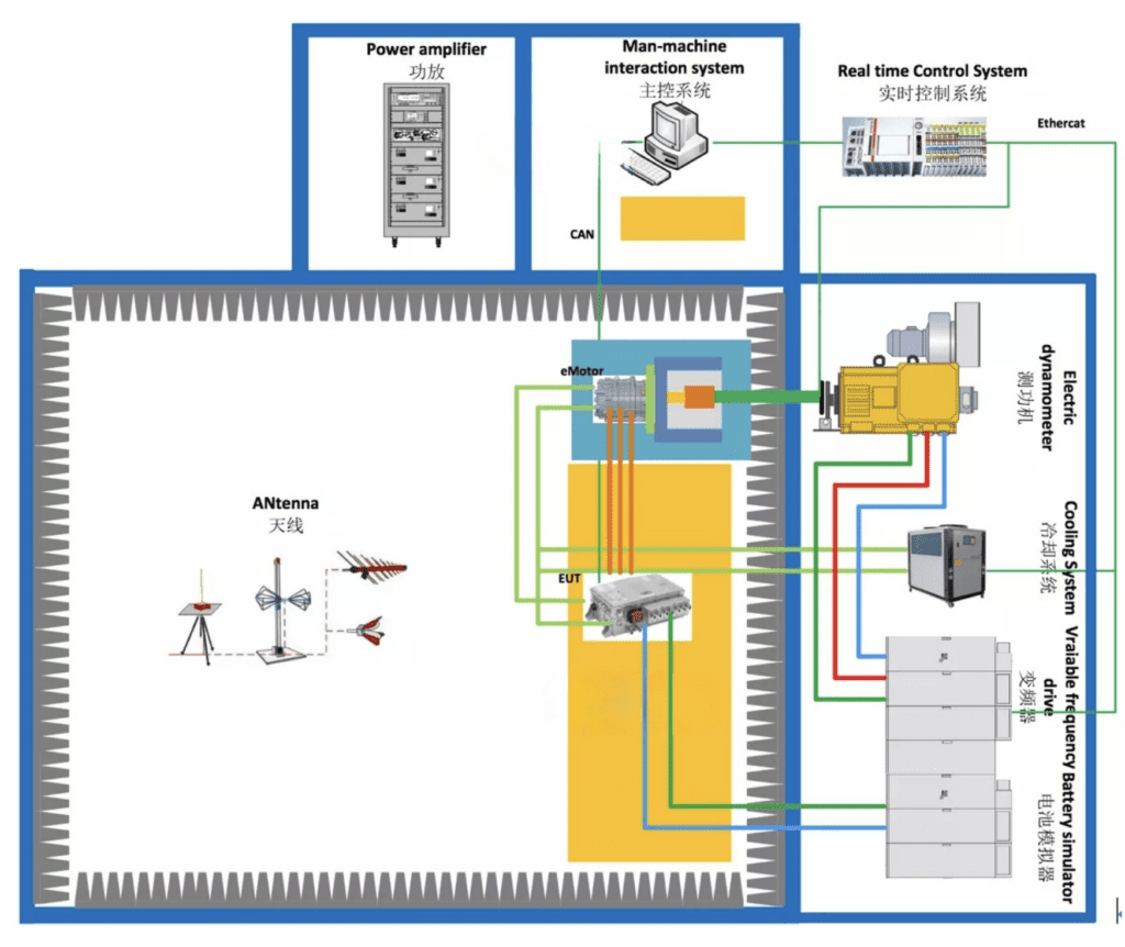
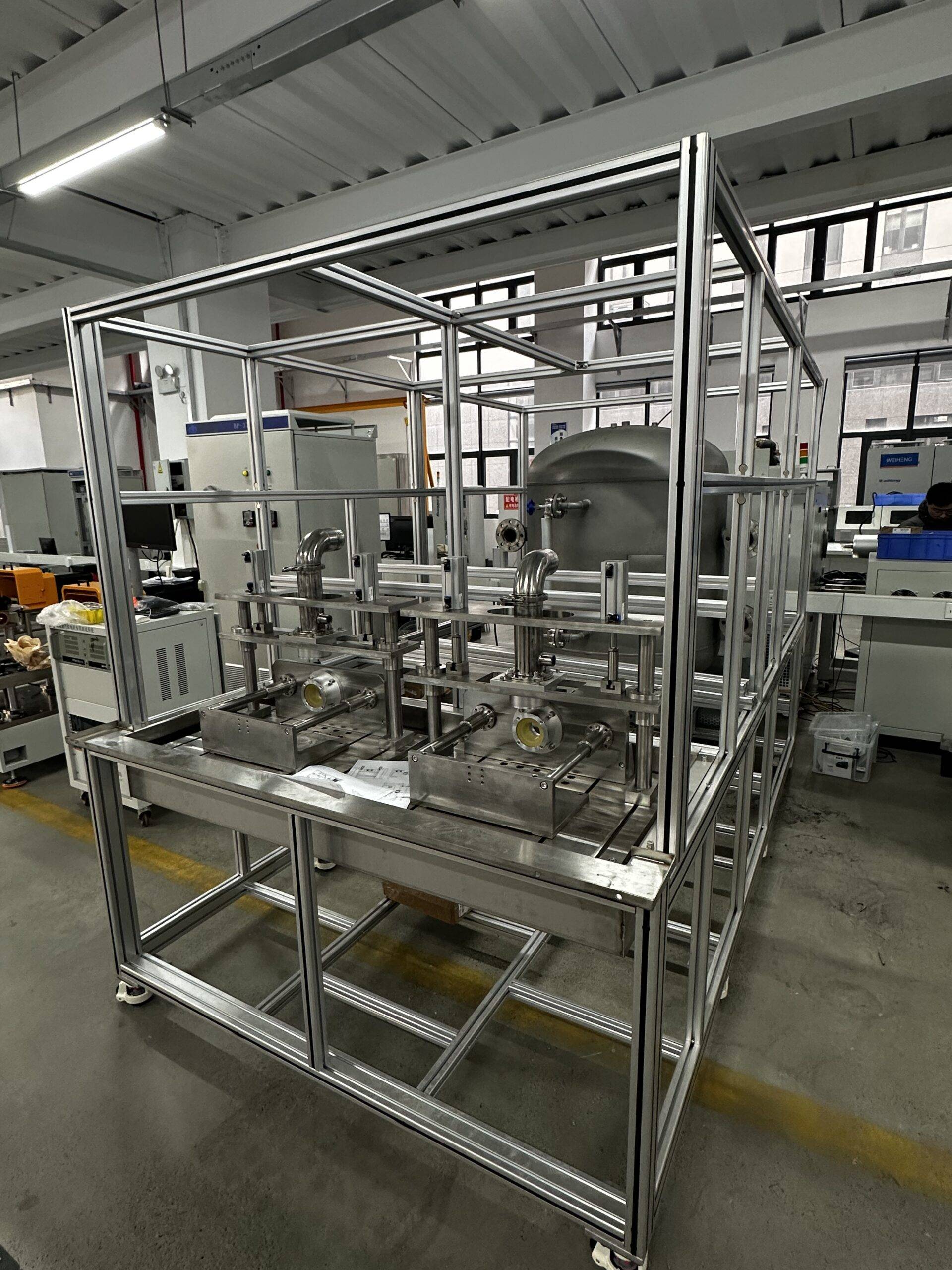
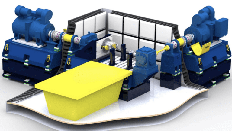
In addition the system utilizes a medium-speed high-torque dynamometer that connects to a dual-output shaft gearbox. Through gear transmission, the high-speed shaft can increase to higher speeds, while the low-speed shaft is directly power by the dynamometer. This flexible configuration allows for testing both high-speed, low-torque и low-speed, high-torque electric drive systems.

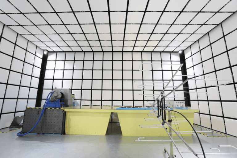
Однако, due to the introduction of a high-speed gearbox, the mounting surface area for the motor will be larger, and the reflecting surface area will also increase. This can lead to a slight impact on measurement uncertainty. To mitigate these effects, our product is equipped with several key design features to ensure optimal performance and accuracy.

key design features

  1. Oil and Gas Absorption Device: The high-speed gearbox fully equips with a device, which prevents oil and gas from volatilizing into the anechoic chamber, maintaining the integrity of the testing environment.

  2. Medium-Speed High-Torque Dynamometer: This dynamometer reduces the gearbox’s transmission ratio, lowers the center distance, and minimizes the gearbox’s cross-sectional area. This design effectively reduces the impact on measurement uncertainty, ensuring more precise test results.

  3. Lubrication System with Power-Failure Protection: The gearbox’s lubrication system equips with a mechanism that continues to supply oil for at least 5 minutes after a power failure, preventing damage to the gearbox due to oil cutoff during testing.

  4. Constant Temperature Lubrication System: The system features a constant temperature device that ensures the oil inlet temperature remains stable. This helps minimize the influence of lubricating oil viscosity on transmission efficiency and eliminates errors in torque measurement caused by fluctuations in transmission efficiency.

These thoughtful design elements ensure that our powertrain testing system delivers accurate and reliable results, even in complex testing scenarios. The system is highly adaptable and capable of addressing a wide variety of electric drive and powertrain testing requirements

EMC

Technical description-1. System Architecture of E-motor EMC testing solution

The electric drive EMC/EMI test system typically consists of an electric wave anechoic chamber, динамометрическая система, and various measuring instruments. We primarily offer the anechoic chamber and dynamometer system.

The anechoic chamber is typically a standard CISPR25 chamber, which designs to ensure accurate testing in controlling conditions. The dynamometer system, on the other hand, customization bases on the specifications of the UUT. It generally includes several key components, such as:

  • A power dynamometer to simulate the load

  • A through-wall shielding shaft system for precise measurements

  • An installation stand for secure positioning

  • A frequency converter to adjust operational parameters

  • A battery simulator to mimic real-world energy sources

  • A cooling system to regulate temperature during tests

  • A sensor measurement system to capture critical data

  • A data acquisition system for processing and recording results

  • Monitoring software for real-time control and analysis

This comprehensive setup ensures that all necessary tests are conducting with high accuracy, helping you meet stringent EMC/EMI compliance standards for electric drives.

Решение EMC EMC EMC

2. Key technical indicators ofСистемная архитектура

2.1 Эффективность защиты-(С) Эффективность экранирования электрического привода EMC Загрузка CISPR25 Darkroom, управляющая комната, and power amplifier room implement in accordance with the standard EN50147-1 or the latest GB/T12190 standard (Частотный диапазон 10 кГц ~ 18 ГГц). The specific test frequency determine in according to the test frequency of the third-party testing agency, which meets the following indicators:

Решение EMC EMC EMC

После установки всех соответствующих аксессуаров (в том числе настенный вал), Электрический привод EMC Dynamometer работает (small non-radiation load can provide), и система мониторинга, лампы, Антенна башня работы, and the filter are active, Эффективность экранирования. Уровень на 10 дБ ниже, чем в классе 5 предел (Пк&QP&ИЗ) specifying by CISPR25.

2.2 Точность управления измерениями 1) Точность измерения крутящего момента: ± 0,05%фс

2) Импульсное разрешение датчика скорости: 1024/600PPRPPR

3) Точность управления крутящим моментом: ± 1%

4) Точность управления скоростью: ± 0,01%фс

5) Максимальное значение скорости вибрации динамометра (RSM): ≤2 мм/с (независимый), ≤3,5 мм/с (загрузка)

6) Повышение температуры промежуточного подшипника: ≤35 ℃

7) Максимальное значение скорости вибрации промежуточного сиденья подшипника (RSM): ≤2 мм/с (независимый), ≤3,5 мм/с (загрузка)

2.3 Долгосрочный метод-(Другой) Согласно последней версии CISPR25, Моделированный метод длинной проволочной антенны (Другой) принимается в диапазоне частот 150 кГц ~ 1 ГГц, и ошибка более чем 90% фактических тестовых точек не более ± 6 дБ по сравнению с теоретическим значением модели. Тестовая площадь-это сторона двигателя и немоторная сторона. Тест приглашает авторитетное агентство измерения сторонних измерений провести тест и предоставить отчет.

Background noise and radio anechoic chamber

2.4 Фоновый шум-(Абн) Когда нет дачи, Система мониторинга, лампы, and filters are active, В диапазоне 9 кГц ~ 6 ГГц, Уровень теста фонового шума должен быть как минимум ниже, чем уровень класса 5 предел (Пк&QP&ИЗ) указано в последней версии CISPR25 10DB, что по меньшей мере на 6 дБ ниже, чем предел GJB151B Re102. This test invites third-party measurement institutions to certify by the state to conduct tests and provide reports.

2.5 Air quality After the construction of the radio anechoic chamber complete, once an inspection agency with CNAS and CMA qualification, it should invite to conduct air quality testing in the darkroom, in addition to issue a test for the air quality in the darkroom. such as (в том числе хотя бы формальдегид, бензол, толуол, Диметилбензол и TVOC) Отчет, however the test results meet the limit requirements, such as: GB50325-2010 \”Правила контроля загрязнения окружающей среды в помещении ” и GB/T. 18883-2002 \”Indoor Air Quality Standards\”.

2.6 Grounding resistance The anechoic chamber and shielding room grounding by single-point floor, in addition we design and construct the grounding resistance. with grounding device process uses physical resistance reducers, но не использует восстановители химической устойчивости. Maintainable with our grounding. The grounding resistance of dark room and shield room is less than 1Ω.

3. Стандарты реализации

1. CISPR16-1-4 \”Технические характеристики для радиопомех и тестового оборудования и методов иммунитета 1-4: Radio Interference and Immunity Test Equipment with Interference by Auxiliary Equipment\

2. CNAS-CL01-A008 \”Инструкции по применению критериев компетенции лаборатории тестирования и калибровки в области тестирования электромагнитной совместимости ”

3. EN50147 \Measurement method of shielding effectiveness of high-performance Shielding room\

4. ГБ/т 12190 \”Measurement Method of Shielding Effectiveness of Electromagnetic Shielding Room\

5. Iso 4589-2 \”Пластмассы определение сжигающего поведения с помощью индекса кислорода 2: Ambient-temperature test\

6. ГБ/T2406 Метод испытания на производительность сгорания пластика.

7. ГБ 8624 Классификация сжигания строительных материалов и продуктов;

8. Iso 11452-1/-2/ Road vehicles-Test methods for immunity of electronic/electrical components to narrowband, which with radiate electromagnetic energy-Radio anechoic chamber method;

9. Циспр 25 Ограничения и методы измерения характеристик радиосвязанного нарушения транспортных средств, Ships and Internal Combustion Engines use to Protect Vehicle-mounted Receivers.

10. MIL-STD-461G Требования к управлению электромагнитными интерференционными характеристиками подсистем и оборудования

11.GJB 151b “Требования и измерения для электромагнитного излучения и чувствительности военной техники и подсистемлей”

12.ГБТ 36282-2018 Система двигателя электромагнитной системы электромагнитной работы. Требования к электромагнитной совместимости и методы испытаний.

13.ГБ 50325-2010 “Кодекс для контроля загрязнения окружающей среды в помещении гражданского строительства

14.GB/T18883-2002 Indoor Air Quality

4. Key technology description

The key technologies of the EMC test system for motors and drives include: высокоскоростной стены, Полная система электрической изоляции, Система мониторинга датчиков в темной комнате, Симулятор батареи с низким шумом и другие системы, Система мониторинга в реальном времени и другие детали.

4.1 Высокоскоростной сквозь стенку

Решение EMC EMC EMC
Решение EMC EMC EMC

CISPR25 определенный макет теста

The CISPR25 standard clearly requires that the distance between the controller EUT, and the center of the absorbing material is not less than 1m.

Для сборки электрического привода из трех в одном, however the distance between the inner side of the controller (Рядом с темной комнатой), and the top of the absorbing material is not less than 1M, in addition the distance between the mounting end of the motor drive assembly, furthermore the top of the absorbing material is not less than 1M.

Чтобы удовлетворить это требование, Длина системы вала длиннее, И в то же время, Он должен соответствовать требованию меньшего вибрации на высокой скорости. with current solution is to use carbon fiber shaft or glass fiber shaft, Условия испытаний требуют, чтобы длина вала была больше, чем 1.6 метры. (international standards stipulate that the distance between the end face of the motor, and under test and the top of the anechoic chamber absorbing material is not less than 1M.

Material environment:

Considering the absorbing material Thickness, толщина феррита, и толщина щита, Принимая во внимание ошибку во время установки). Although these two non-metallic shafts are excellent materials, which are non-conductive and non-magnetic, Поскольку система электрического привода новых энергетических транспортных средств вышла на стадию высокоскоростной и высокой вершины, Абсолютный упругой модуль стеклянных волокон или валов углеродного волокна не подходит для высокоскоростных и высоких испытаний. Сцены.

The high-speed through-wall shielding shaft designs by ourselves, which has the following characteristics:

  1. Принять высокий режим и жесткий вал с низкой инерцией, Принимая во внимание характеристики высокой скорости и большого крутящего момента.
  2. Как часть анехозной камеры, Вращающийся вал имеет хорошую проводимость, принципиально защищает внешнее электромагнитное излучение, достигает превосходного экранирующего эффекта, и уменьшает фоновый шум в темной комнате.
  3. Через съемную экранирующую крышку, the test motor can be completely shielding, and the electromagnetic compatibility characteristics of the drive axle can test independently.
Решение EMC EMC EMC

High-precision long-axis system

Чтобы соответствовать высокоскоростному, Требования к большому точковому и экранированию одновременно, Система принимает высокую систему с длинной осиной.

  1. Скорость вибрации в диапазоне полной скорости составляет менее 3,5 мм/с..
  2. Система вала использует многоточечную структуру поддержки, что удобно для центрирования основания в темной комнате, а коаксиальность лучше 0,02 мм.
  3. Система вала имеет полностью динамическую структуру баланса, и точность динамического баланса достигает G1.
  4. Критическая скорость первого порядка системы вала выше максимальной скорости системы. 4.2 Полностью электрически изолированная система
  5. In order to prevent electromagnetic waves and charges from conducting outside the anechoic chamber to the anechoic chamber, В дополнение к специальным методам электромагнитного экранирования, динамометр должен быть полностью изолирован. Электрические двигатели или трансмиссии должны соответствовать требованиям заземления с одним точкой.

    1. The dynamometer and the shielding shaft adopt high-speed insulation coupling.
    2. The dynamometer is completely electrically isolating from the base.
    3. Высокоскоростная shielding shaft and the tested electric drive motor shaft adopt high-speed insulation coupling.
    4. The installation base in the anechoic chamber is completely electrically isolating from the anechoic chamber.
    5. The anechoic chamber designs with a removable complete shielding cover, который может полностью защитить двигатель и проверить EUT контроллера индивидуально.

4.3 Non-radiation sensor monitoring system in dark chamber room

The electric drive system and shaft system under test in the anechoic chamberhowever design with vibration and temperature monitoring sensors. The sensors need to collect by a high-speed data acquisition system and transmit to the monitoring software for signal analysis and processing.

With data acquisition system is placed in the anechoic chamber. Из -за собственного излучения, affect the background noise of the anechoic chamber, and low noise processing is requiring.

Наша компания сделала следующие проекты для системы сбора данных в анехозной камере:

  1. Питание системы сбора данных фильтруется фильтром 24 В для устранения интерференции питания, входящих в электрическую темную комнату.
  2. Конструкция передачи сигнала системы сбора данных. Конвертер оптического волокна в реальном времени в реальном времени, Через оптическое волокно и оптическое волноволод, установленные на стене анехозной камеры, передает сигнал в анеховую камеру, а затем преобразует его в цифровой сигнал через обратный преобразователь, и входит в верхнюю позицию в машине.
  3. Система сбора данных установлена ​​в экранированной коробке. Экранированная коробка предназначена с вентиляционными волноводами, чтобы обеспечить рассеяние тепла и в то же время гарантировать, что электромагнитные волны в коробке не будут переданы в темную комнату.
  4. Кабель датчика принимает специальный экранированный кабель, который соединяет датчик и экранированную коробку в целом.

4.4 Симулятор батареи с низким уровнем шума

Симулятор аккумулятора обеспечивает тестовую мощность контроллеру двигателя, so it can simulate the battery, и также может выполнить тесты заряда аккумулятора и разрядки.

1. Выходное напряжение:

  • Максимальное выходное напряжение (ШЕСТЬ): 1200V.
  • ВЫХОДА РАСПРОСКОЕ ОТДЕЛЕНИЕ: 20V ~ unom регулируется, Установка разрешения: 0.1V.
  • Повторяемость: ≤0,1% шесть
  • Время повышения напряжения (10% к 90% ШЕСТЬ): <5РС (резистивная нагрузка)
  • Смена нагрузки (10% к 90%) Время управления: ≤1 мс (резистивная нагрузка)
  • Остаточная волна: ≤0,2% неоплачиваемого эффективного значения (Частота DC-1MHZ)

2. Выходной ток:

  • Максимальный выходной ток (В пределах): 800А
  • Выходной диапазон тока: 0~ Инома регулируется, Установка разрешения: 0.1А
  • Повторяемость: ≤0,1% внутри
  • Текущее время нарастания (10% к 90% В пределах): <1РС (резистивная нагрузка)
  • Смена нагрузки (10% к 90%) Время управления: ≤1 мс (резистивная нагрузка)
  • Температурный коэффициент: ≤0,01% внутри/k
  • Остаточная волна: ≤0,2% эффективное значение иннома (Частота DC-1MHZ)
  1. Выходная мощность: ‡ 350 кВт
  2. Эффективность выходной системы: >90%
  3. Точность вывода: 0.1%
  4. Внутреннее сопротивление:
  • Настройки диапазона: 0~ 5W (Регулирование разрешения 0,1 МВт)
  • Режим батареи: Регулируя внутреннее сопротивление

The parameters of the battery simulator can customize according to customer‘s needs.

4.5 Система мониторинга в реальном времени

The monitoring system adopts embedding real-time controller control, Коммуникация Ethernet в реальном времени, и все коммуникационные кабели, попадающие в контрольную комнату, передаются через оптические волокна.

  1. Мониторинг переднего и заднего подшипника в реальном времени и температура динамометра, Мониторинг тока и напряжения динамометра в реальном времени, и мониторинг скорости и крутящего момента динамометра в реальном времени.
  2. Защитите мониторинг вибрации длинной оси в реальном времени.
  3. Мониторинг тестирования мотора в режиме реального времени в режиме реального времени.
  4. Электронная система управления имеет функции защиты, такие как короткий замыкание, утечка, сбой питания, перегрузка, и перенапряжение.
  5. Системное программное обеспечение имеет функцию обнаружения безопасности. Когда значение мониторинга превышает порог, это сразу же будет тревожить. Система имеет три уровня защиты.
  6. Темная комната принимает неэлектромагнитную радиационную фотоэлектрическую систему сбора данных об изоляции, который собирает датчик вибрации и датчики температуры в реальном времени, и передает их в контрольную комнату через оптическое волокно для мониторинга в реальном времени.
  7. Кнопки экстренной остановки разработаны рядом с испытательным столом в темной комнате, в контрольной комнате, возле динамометра, и т. д..
ошибка: Контент защищен !!