

Wir stellen die Torquemeter zur Verfügung, Kupplungen, Schwungräder, Spindeln & Prüfstände für die Prüfung von Hubschrauber- und Flugtriebwerkskomponenten

Wir bieten eine Testlösung für Meeresmotoren, Antriebssysteme, Elektromotoren, Generatorsätze, Getriebegetriebe, Hilfsstromsysteme, Abgassysteme, und Ersatzteile für Schiffe
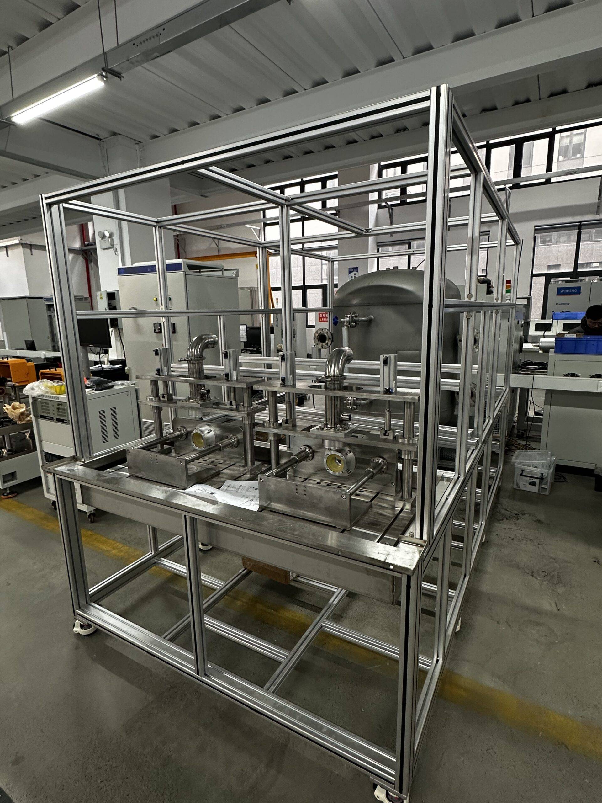
Das Wasserpumpenprüfsystem ist ein spezielles Gerät, das für die Leistung von Wasserpumpen verwendet wird, häufig verwendet, um Schlüsselparameter wie Fluss zu bewerten, Kopf, Leistung, und Effizienz.

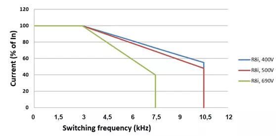
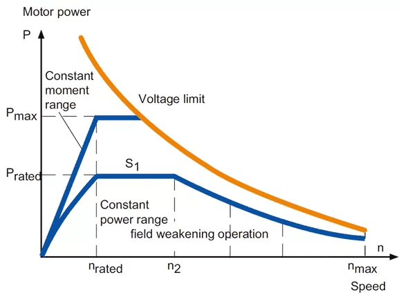
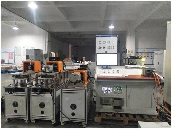
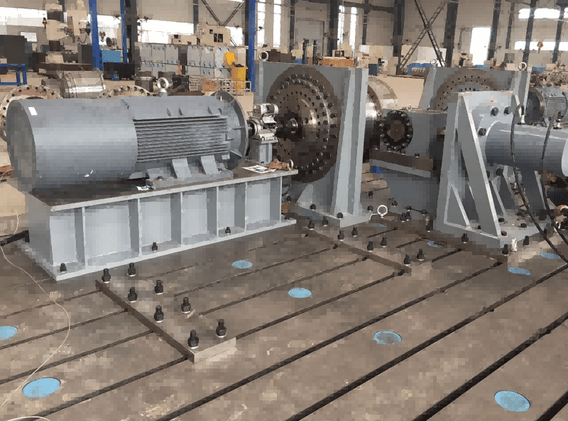
Die Hochgeschwindigkeitsmotor-Prüfstand ist ein spezielles System zur Bewertung und Validierung der Leistung von Hochgeschwindigkeits-Elektromotoren unter verschiedenen Betriebsbedingungen. Es besteht aus mehreren Schlüsselkomponenten, einschließlich eines Dynamometers, Echtzeit-Controller, Datenerfassungssystem, und verschiedene Sensoren
Planetenreduktionsprüfstand, Harmonische Reduzerprüfstand RV Reduder -Prüfstand Reduzier-Testbänke mit viererer Serie
![]()
© 2026 Shanghai EconoTechnology Co., Ltd. Alle Rechte vorbehalten.
Förderung von Innovationen durch zuverlässige Testlösungen.