Powertrain systems primarily relay on transmission concepts before, such as manual, automatisch, and dual-clutch Übertragungen for 2WD and 4WD vehicles. Jedoch, with the transition to fully electrified propulsion systems, the modern one has undergone a fundamental transformation. In addition electric drives and high-voltage components have become central to these systems.
Supporting development and system integration, Usually customers require cutting-edge test systems, which are capable of evaluating and optimizing both the mechanical, high-voltage electrical subsystems. Our state-of-the-art propulsion test systems design to validate a wide range of configurations, including different types 2WD and 4WD systems, speeds, Drehmoment, power classes, as well as high-voltage and current requirements specific to electrified systems.
Furthermore it also incorporates steering capabilities, enabling comprehensive vehicle-in-the-loop (VIL) Testen. This approach creates a highly realistic testing environment,which essential for validating the functionality of advanced driver assistance systems (ADAS) and automated driving (AD) technologies in real-world vehicle applications.

Mobilel/Portable axle-mounted dynamometers have become essential tools, which is in the automotive industry for assessing powertrain performance, moreover they provide the flexibility and precision in modern vehicle testing. These dynamometers enable engineers to measure Leistung Und Drehmoment in various locations, whether in workshops or within environmental chambers, providing valuable data throughout different stages of vehicle development. Therefore the adaptability ensures that manufacturers can optimize performance, verify the vehicles meet the necessary regulatory standards.
When launch in environmental chambers, portable axle-mounted dynamometers greatly enhance the ability, in order to test vehicle performance under controlled conditions. Environmental chambers can simulate a wide range of climatic scenarios, including extreme one (from -45°C to 65°C) and varying levels of humidity, all of which can significantly impact a powertrain’s Effizienz Und Emissionen. By integrating dynamometers into these chambers, manufacturers and researchers can conduct performance tests, that offer valuable insights into how different environmental factors influence vehicle operation. With controlled testing is crucial for ensuring vehicles can meet Emissionen, Und performance standards in diverse and challenging conditions, ultimately helping to ensure their reliability and compliance across various markets.
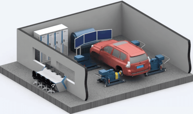
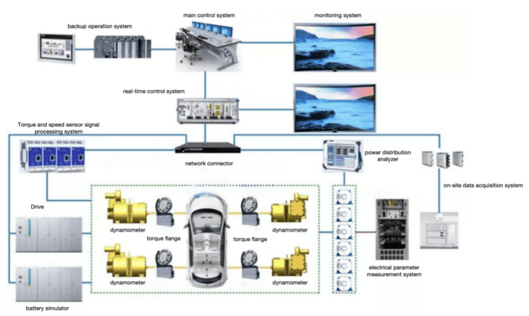
Powertrain/Hub-coupled powertrain Test Bench compose several key components, each design to ensure accurate and efficient testing of vehicle powertrains. These components include:
Mobile Low-Inertia Electric Dynamometer: The dynamometer provides precise speed and torque control, simulating real-world road load conditions. It is capable of rapid response to dynamic changes, making it ideal for simulating varying road conditions. Load simulation methods include:
Constant torque control
Calculated road spectrum simulation
Actual road spectrum import
User-defined load spectrum
Dynamometer Driver: This part controls dynamometer’s operation, allowing it to simulate different load scenarios and accurately replicate road conditions.
Battery Simulator: Use to simulate the electric vehicle’s battery, in addition the simulator can replace the actual battery, providing accurate power outputs for testing. It supports the evaluation of energy consumption and efficiency in the drivetrain.
Electrical Control Cabinet: Cabinet houses the control systems for managing the dynamometer, Batteriesimulator, and other electrical components. Acts like a crucial role in regulating the overall system operation.
Measurement Sensors: These sensors monitor various parameters during testing, such as temperature, Druck, Drehmoment, Geschwindigkeit, and vibrations. Moreover provide real-time data for analyzing the performance and efficiency of the vehicle’s powertrain.
Vehicle Windward Cooling System: Cooling system ensures the vehicle’s powertrain operates within optimal temperature ranges during testing, helping to prevent overheating during prolonged tests.
Traffic Real-Life Simulation System: Solution integrates with the dynamometer to simulate real-world traffic and road conditions. Which mimics driver actions and varying road conditions, including different terrain and vehicle speeds, Gaining a more realistic and comprehensive test environment.
Main Control Computer: The central hub for system operation, the computer manages all the test processes, coordinates data acquisition, allows for the adjustment of test parameters. which also analyzes the results and generates performance reports.
Energy Flow Analysis (Power Analyzer): The power analyzer measures the current, Stromspannung, and power consumption of each energy unit in the test vehicle. Moreover it provides insights into the energy flow across different operational modes, creates an energy spectrum for the entire vehicle. As a result help in evaluating the overall efficiency of the powertrain.
In addition system allows for flexible transformation into a powertrain test system. By connecting the Batteriesimulator to the powertrain drive, solution can test the powertrain’s performance under various conditions, simulating energy consumption and power distribution throughout the drivetrain components.
Therefore architecture enables the thorough testing of vehicle powertrains, ensuring that all components work efficiently under different real-world conditions.
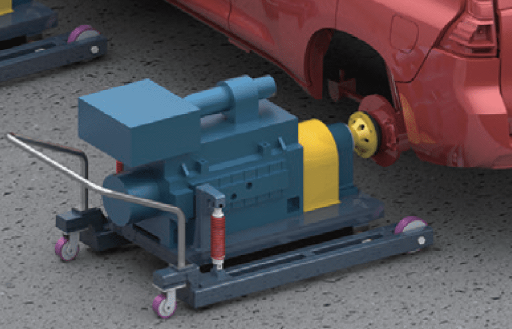
The shaft coupling dynamometer adopts a flexible design with a movable mode. The dynamometer and vehicle hub take a quick connection structure, therefore the user can quickly complete the connection between the vehicle and the dynamometer. The tray bracket of dynamometer support by universal wheels, which can move conveniently, at the same time it also simulate the actual steering function.
The flange shaft connect to the wheel hub of the vehicle adopts a hollow structure,in order to minimize the moment of inertia of the shaft system, improving the dynamic response capability of the dynamometer system. A transitional connection flange designs between the flange and the wheel hub of the vehicle, as the flange also adopts a weight reduction design to reduce the moment of inertia.
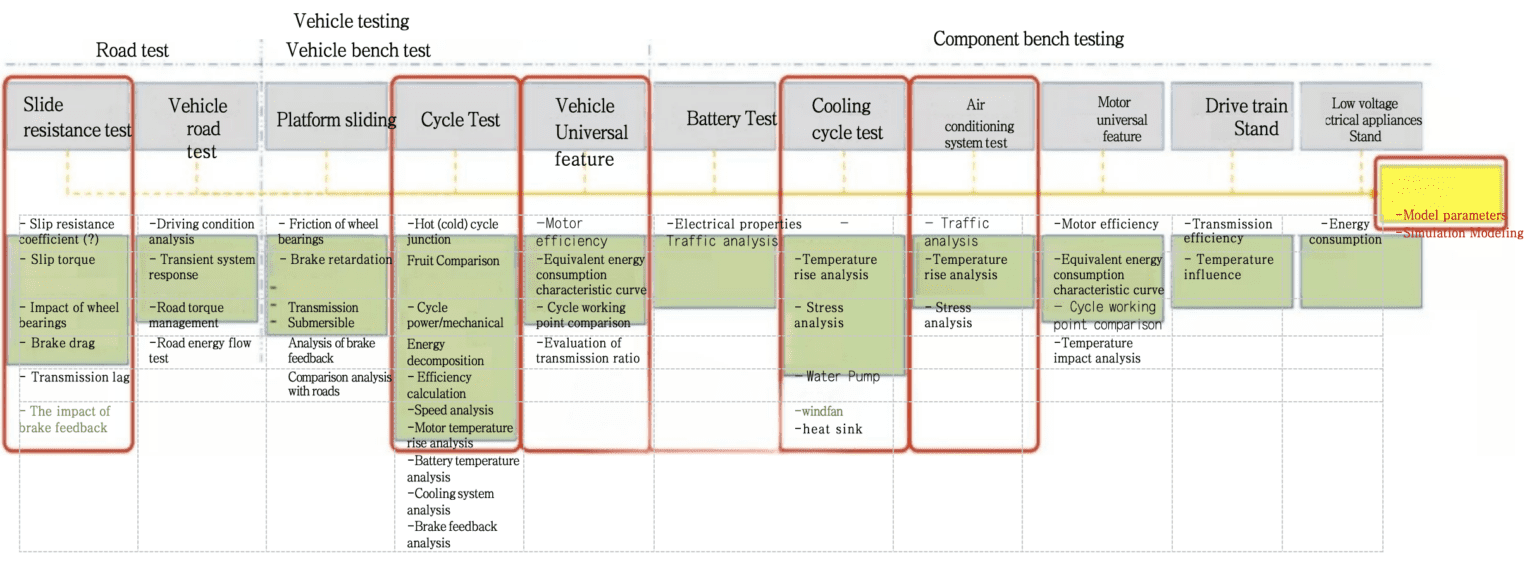
Axle-coupled dynamometer is a flexible test system with a very high degree of flexibility. Users can combine tests at will, moreover can test four-wheel drive and two-wheel drive vehicles, separating electric drive powertrain tests. The shaft coupling dynamometer adopts a motor with extreme low inertia, moreover the real-time Ethernet communication control. Solution obtains a very high dynamic response speed, which complete the dynamic alternating working condition test of the load. The shaft coupling dynamometer system has the following functions:
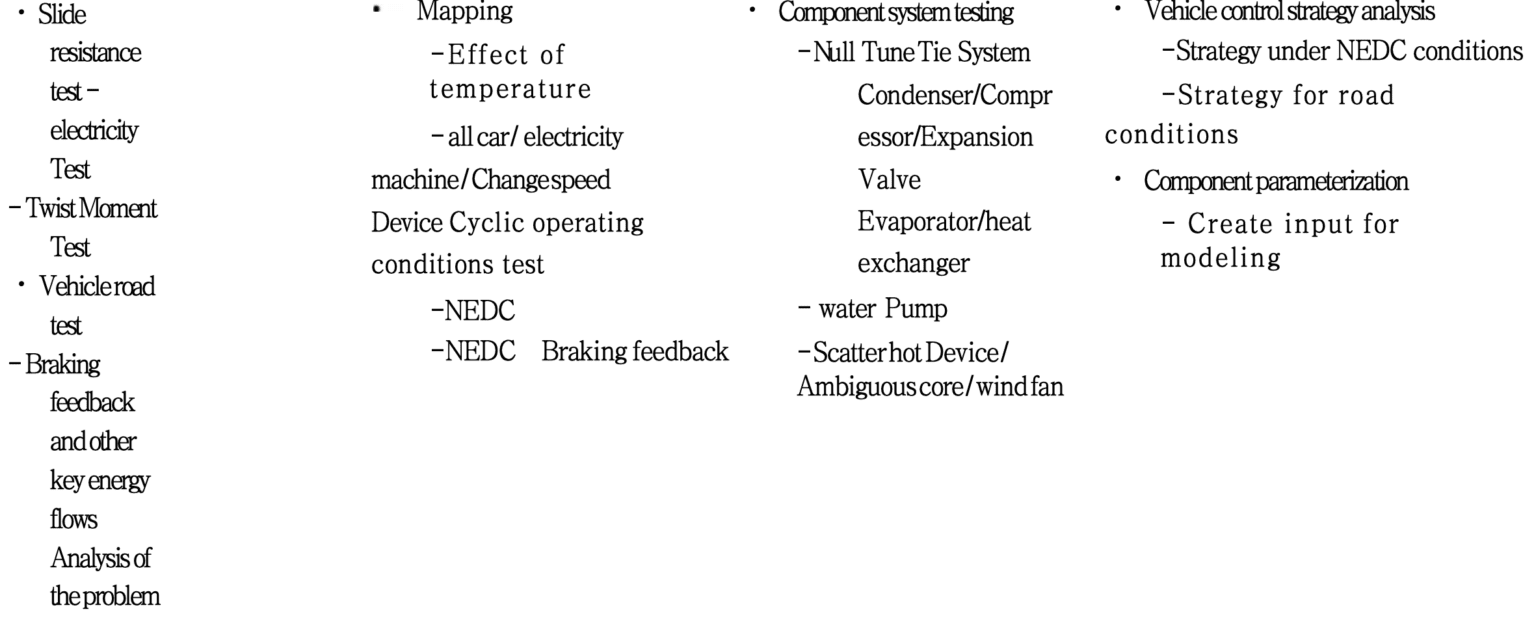
1. Vehicle durability test, energy flow test, energy consumption test, acceleration test, road simulation test, braking performance test, Fehlererkennung, conformance test, braking energy recovery test
2. Test of universal characteristics of the whole vehicle
3. Driver in the loop test
4. Development and calibration of vehicle control strategy
5. Powertrain efficiency test, speed and torque characteristic test, Temperaturanstiegstest, controller control strategy development verification test, braking regenerative energy feedback test, external characteristic test, development matching optimization test, performance test and calibration test
6. Efficiency Map Test
7. Accelerated response test
8. Torque response test
9. Durability test of steady-state cyclic loading
Base on the specific vehicle configuration, working conditions and working mode, the energy generate and transfer/convert from the power source to the wheel end.
2) Energy transfer efficiency/loss:
In the energy transmission path, the lossy systems and components, with corresponding energy consumption form. The quantified energy consumption distribution for energy consumption systems and components.

The key points of the vehicle energy flow test are the accuracy of the measurement, the synchronization of the measurement of different energy-consuming components, as well as the authenticity of the vehicle condition simulation.
In order to improve the accuracy of electric energy measurement, it is necessary to configure a high-precision power analyzer and transformer, use a power analyzer with a high-precision synchronous clock function, in order to synchronously collect and measure the signals of each sensor.
Vehicle energy flow test:
The software system mainly divide into the following parts:
★Test management software: Basic parameters and relevant control parameter settings require before operation, generate test information files, and name by the test main control software.
Through the interaction with the real-time control computer during the test, the process automatically manage and the specify via real-time information is process.
After the test finishing, test reports, test record retrieval, data post-processing, usw. can provide to the users.
★Real-time control software of test bench: Through the acquisition of close-loop control sensor, and through interaction with the test management, computer obtains the upper-level solved control parameters. Providing the necessary lower-level calculations, real-time close-loop control of the speed, as well as torque of the driving and loading motors with other Real-time control of auxiliary facilities.
A unified human-computer interaction interface, which integrates the main information on the same machine; real-time display of test progress, main test data, the status of the test piece, test bench and other information.
★Test data acquisition and post-processing software: The system provides various mathematical operations of data, including subtraction, multiplication, division, integration, differentiation, maximum value, minimum value, peak value, RMS, average, sum, usw.
All software systems adopt modular design, with good flexibility and scalability. Main functional modules of the software are: main program framework module, system control module, data acquisition module, data recording module, data analysis module, data display module, communication module, data playback module, print processing module, sensor calibration module, function setting module, Help document module and data post-processing analysis module, usw.
After the vehicle has undergone the loss calibration and coasting test, the formal test carry out. At this time, the simulated load of the dynamometer is similar to the road load of the vehicle.
Before the user starts for the device for testing, the device needs an effective friction calibration (the device will only be used if it exceeds a certain speed corresponding to the friction calibration). In addition user can check the calibration status through the dial control page that displays the calibration status.
Users can perform friction calibration regardless of whether the vehicle is equipped or not, but the system cannot distinguish between equipment friction loss and vehicle loss at this time. Therefore the user needs to make a new loss calibration for each new car. It recommends to do friction calibration where the vehicle is not equipped.
At the same time, the user considers the friction loss will change with the adjustment of the ambient temperature. daher, it is necessary to warm up the device, before friction calibration or test and maintain its temperature until the end of the test.
When the vehicle loss calibration till end, the page will automatically update and display the maximum calibration speed. The calibration of friction loss can analogize to the calibration of vehicle loss. Maximum calibration speed show the lower of the friction calibration speed and the vehicle loss calibration speed.
5.4 Basic inertia calibration
The basic inertia calibration used to calibrate the basic inertia of the test bench, einschließlich: the total moment of inertia of each transmission system, such as the drum, drive shaft, and motor. The basic inertia calibration is a necessary condition for the correct operation of the test bench.
In the taxiing process, the system first accelerates device to above the maximum speed required for taxiing, furthermore it enters the road simulation mode until the device is below the minimum speed required for taxiing. Additionally it passing the designated speed point, the moment Will be recorded. After system can accurately calculate the road simulation by calculating the time, moreover the average deceleration force for the specified taxi distance. Users can find this information on the taxi results page.
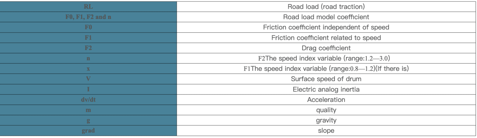
The system can provide various dynamometer electromechanical inertia simulation, and simulate the road load according to the equation:
Für Fragen oder Unterstützung, Bitte kontaktieren Sie uns per E-Mail unter [email protected].
Wir sind bestrebt, zeitnah zu reagieren.
Brauche sofortige Hilfe? Rufen Sie uns an +86 156 1877 0706.
Unser Team steht Ihnen gerne zur Verfügung.
Wir heißen Sie herzlich willkommen, unser Büro unter zu besuchen 3F, Gebäude 2, Nr. 511 Xiaowan Road, Fengxian, Shanghai, China.
Lassen Sie uns Ihre Bedürfnisse persönlich besprechen.
![]()
![]()
© 2025 Shanghai EconoTechnology Co., Ltd. Alle Rechte vorbehalten.
Förderung von Innovationen durch zuverlässige Testlösungen.