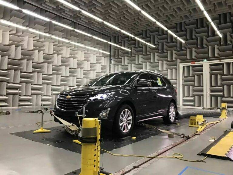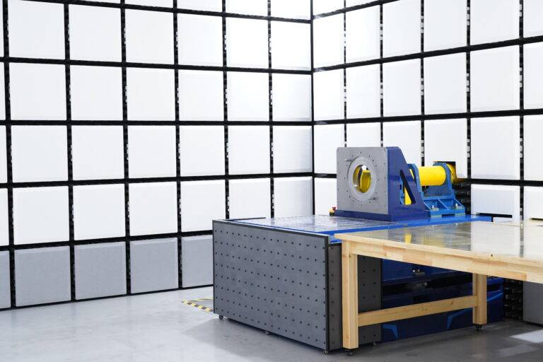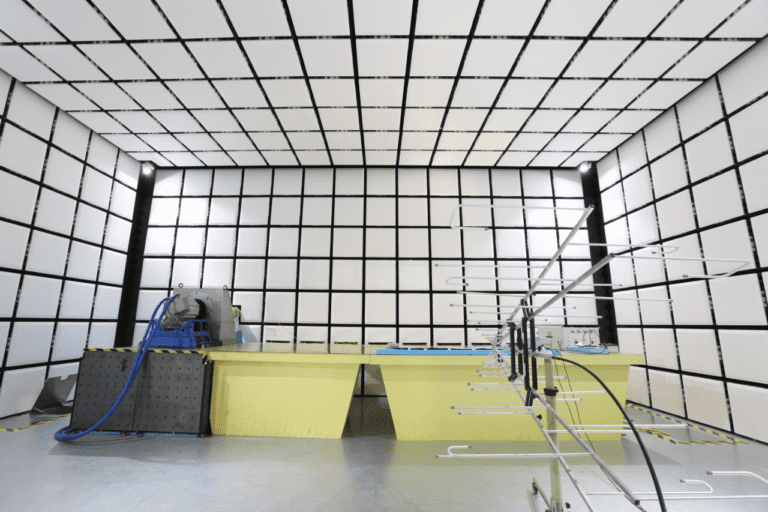
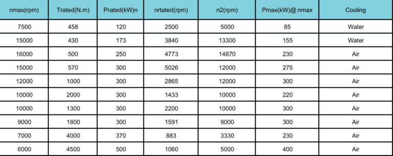
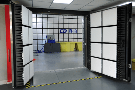
Nostro banchi dinamometri universali per azionamento elettrico e propulsione utilizzare per una varietà di esigenze di test, tra cui Test EMC/EMI per motori ad alta velocità, inoltre propulsori a bassa velocità e coppia elevata, inoltre motori a bassa velocità e coppia elevata. Questo sistema versatile è perfetto per valutare l’intera gamma di sistemi di azionamento elettrico in condizioni reali.
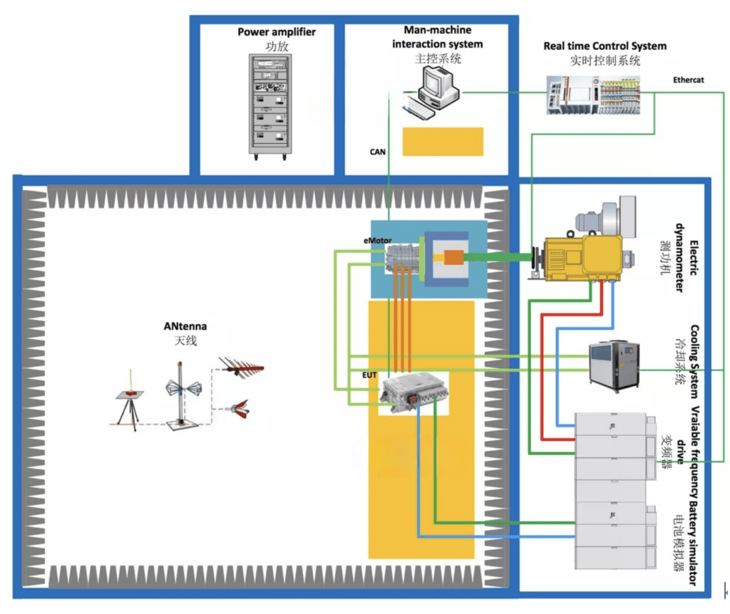
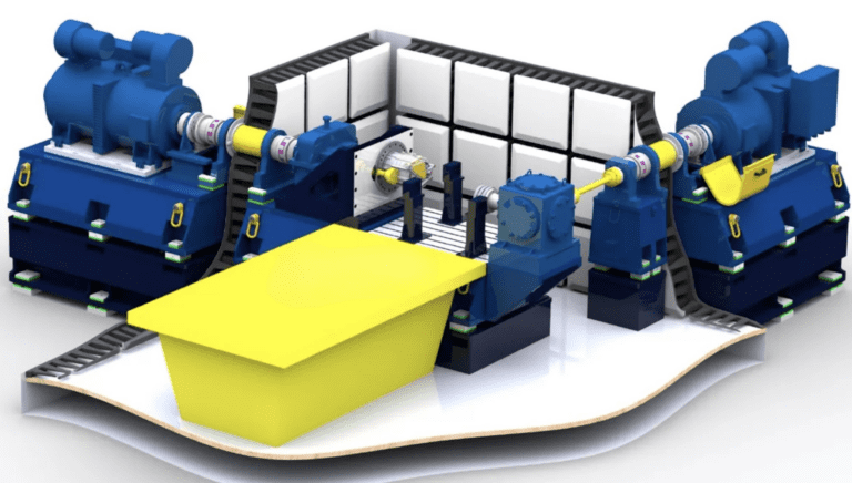
Inoltre il sistema utilizza a dinamometro a coppia elevata a velocità media che si collega a a cambio ad albero a doppia uscita. Attraverso la trasmissione ad ingranaggi, l'albero veloce può aumentare a velocità più elevate, mentre l'albero lento è azionato direttamente dal banco dinamometrico. Questa configurazione flessibile consente di testare entrambi ad alta velocità, bassa coppia E bassa velocità, alto sistemi di azionamento elettrico.
Tuttavia, a causa dell'introduzione di un cambio ad alta velocità, la superficie di montaggio del motore sarà maggiore, e aumenterà anche la superficie riflettente. Questo può portare ad un leggero impatto sull’incertezza di misura. Per mitigare questi effetti, il nostro prodotto è dotato di diverse caratteristiche di progettazione chiave per garantire prestazioni e precisione ottimali.