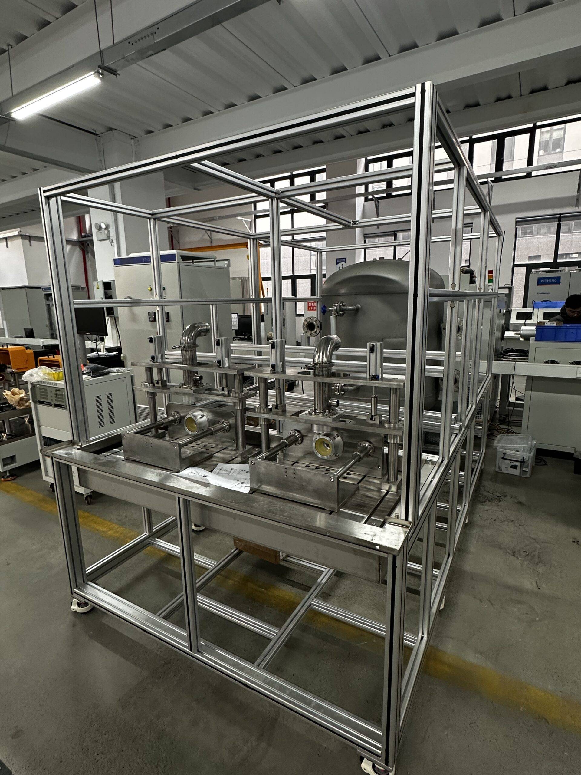
产品

E-motor EMC testing solution

Our e-motor 电磁兼容 testing solution are tailored to meet the growing demands for compliance and performance testing across industries such as automotive, marine, and aerospace. These solutions are both cost-effective and efficient, ensuring consistent and repeatable test results across a variety of setups and configurations.

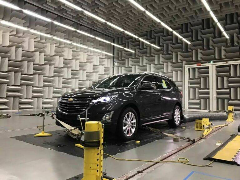
We offer full vehicle test setups equipped with multi-axle chassis load machines, four-wheel drive capabilities, fully automated remote antenna positioning, and specialized charging mode test configurations. This flexibility makes our solutions ideal for testing not only complete vehicles but also Electric or Electronic Sub-Assemblies (ESA), covering a wide range of applications.

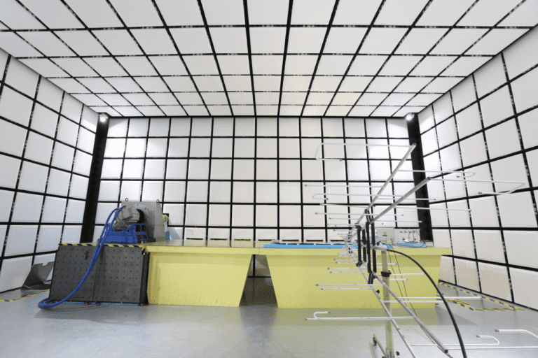
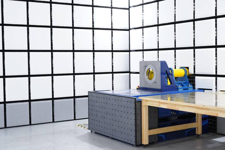
One standout feature of our load machines is the conventional through-shaft EMC chamber installation, designed to meet the CISPR 25 standard. This installation is perfect for testing e-motors ranging from smaller 20 kW units found in motorcycles to larger 700 kW systems commonly used in commercial vehicles. It ensures a thorough evaluation of all dynamic e-motor requirements, helping to accurately assess performance characteristics.

For situations where a permanent load machine installation isn’t feasible, we provide mobile testing equipment as a flexible alternative. This mobile setup can be used in multi-purpose or existing EMC chambers, offering the same comprehensive capabilities and functionality as our stationary systems, though with a slightly limited power capacity range.

Our solutions are designed to ensure you can meet the highest standards of performance and compliance, all while maintaining flexibility and cost-efficiency for your testing needs.

1.E-motor EMC testing solution: Direct drive connection testing type

The direct drive system is designed for performing precise EMC/EMI tests on high-speed motors and controllers. This system is ideal for testing both separate motors and controllers, as well as integrated motor-controller units.

In the setup, high-speed motors are mounted on the end face of an L-shaped tooling or T-slot platform, while the controller is placed securely on the test table. This versatile configuration allows for thorough testing of individual components or integrated systems.

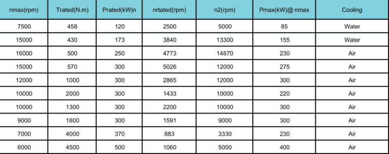
The system can be customized to match the specific parameters of the motor being tested. Depending on the motor’s size and requirements, the appropriate dynamometer can be selected. Below are the recommended dynamometer parameters for optimal testing performance:

All the parameters can be customized depends on the requirement, the solution can be integrated with gearbox in order to output more torque.

2.E-motor EMC testing solution: Mobile/ Portable e-motor EMC testing

电磁兼容

mobile portable e-motor EMC testing solution is an innovative addition to our comprehensive range of load machine options for electric vehicle (EV) component EMC testing. This mobile setup features an EMC load machine with advanced drive electronics and controls, all contained within a shielded, free-standing mobile unit.

The system supports full four-quadrant (4Q) operation, allowing for testing of both the e-motor drive and regenerative functions. It is designed to meet all current emission and immunity standards, ensuring the highest quality of the testing environment with no compromises.

Key Advantages:

One of the standout benefits of this mobile e-motor EMC testing solution is its flexibility. It can be used in existing EMC chambers typically designed for testing consumer electronics or complete vehicles, which means minimal adjustments to the testing environment. This makes it an economical solution for manufacturers looking to streamline their testing procedures.

Many of these chambers already come equipped with essential features like turntablesraised flooring, which facilitate the routing of signal fiber optics and power cables beneath the floor. These built-in features help simplify the setup process and enhance overall operational efficiency.

Streamlined Testing Process:

To maximize efficiency, the Unit Under Test (UUT) can be prepared on the mobile load machine outside the EMC chamber. Once the setup is ready, it can be easily transferred into the chamber using a standard pallet truck, and quickly connected to the power supply. This simple transfer process reduces downtime and ensures more testing time.

Modular and Customizable:

The modular design of the mobile testing platform allows for customization based on specific needs. For instance, if higher speed 或者 torque testing is required, a larger and more capable e-motor and drive unit can be added. This flexibility ensures the mobile solution evolves with the growing demands of manufacturers and researchers, providing a versatile platform for comprehensive EMC testing of e-motor components.

In essence, the mobile e-motor EMC testing solution offers a cost-effective, efficient, 和 flexible approach to testing that can meet the complex needs of the evolving electric vehicle industry.

3.E-motor EMC testing solution: Two-Axis EMC Loading Testing System

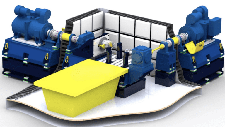
two-axis loading dynamometer system is designed to closely replicate the real-world installation of a vehicle powertrain, offering a highly accurate simulation. This system ensures that the differential is neither locked nor welded, and the output shafts on both sides of the powertrain can be swapped out for on-board half shafts. Additionally, the wheel spacing can be adjusted to match the actual vehicle specifications, providing a realistic testing environment.

This system is particularly well-suited for EMC testing of passenger car motors, with capabilities that include a maximum speed of 12,000 RPM and a rated torque of 1000 N·m. One of its key features is the ability to design the semi-axles on both sides of the powertrain to be insulated from the ground, effectively simulating the behavior of vehicle tires during testing.

For high-speed motor testing, the low-speed shaft side shafting system can be easily removed to facilitate testing of faster motors. Additionally, for scenarios where space is limited in the EMC test chamber, 一个 right-angle transmission box can be used to optimize space and maintain functionality.

This versatile system offers the flexibility to meet a wide range of testing needs, making it an ideal solution for testing e-motors and powertrains in realistic conditions while ensuring accurate EMC/EMI performance evaluation.

4.E-motor EMC testing solution: Powertrain EMC Testing System

我们的 electric drive and powertrain universal dynamometers are designed to handle a variety of testing needs, including EMC/EMI testing for high-speed motors, low-speed high-torque powertrains, and low-speed high-torque motors. This versatile system is perfect for evaluating the full range of electric drive systems under real-world conditions.

The system utilizes a medium-speed high-torque dynamometer that connects to a dual-output shaft gearbox. Through gear transmission, the high-speed shaft can be increased to higher speeds, while the low-speed shaft is directly powered by the dynamometer. This flexible configuration allows for testing both high-speed, low-torquelow-speed, high-torque electric drive systems.

然而, due to the introduction of a high-speed gearbox, the mounting surface area for the motor will be larger, and the reflecting surface area will also increase. This can lead to a slight impact on measurement uncertainty. To mitigate these effects, our product is equipped with several key design features to ensure optimal performance and accuracy:

  1. Oil and Gas Absorption Device: The high-speed gearbox is equipped with a device that prevents oil and gas from volatilizing into the anechoic chamber, maintaining the integrity of the testing environment.

  2. Medium-Speed High-Torque Dynamometer: This dynamometer reduces the gearbox’s transmission ratio, lowers the center distance, and minimizes the gearbox’s cross-sectional area. This design effectively reduces the impact on measurement uncertainty, ensuring more precise test results.

  3. Lubrication System with Power-Failure Protection: The gearbox’s lubrication system is equipped with a mechanism that continues to supply oil for at least 5 minutes after a power failure, preventing damage to the gearbox due to oil cutoff during testing.

  4. Constant Temperature Lubrication System: The system features a constant temperature device that ensures the oil inlet temperature remains stable. This helps minimize the influence of lubricating oil viscosity on transmission efficiency and eliminates errors in torque measurement caused by fluctuations in transmission efficiency.

These thoughtful design elements ensure that our powertrain testing system delivers accurate and reliable results, even in complex testing scenarios. The system is highly adaptable and capable of addressing a wide variety of electric drive and powertrain testing requirements

电磁兼容

Technical description-1. System Architecture of E-motor EMC testing solution

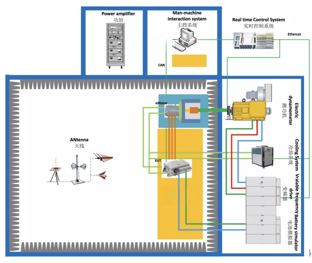
The electric drive 电磁兼容/EMI test system typically consists of an electric wave anechoic chamber, 测功机系统, and various measuring instruments. We primarily offer the anechoic chamber and dynamometer system.

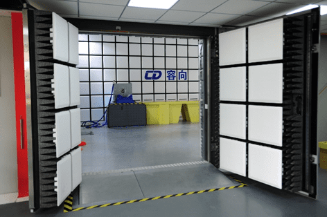
The anechoic chamber is typically a standard CISPR25 chamber, designed to ensure accurate testing in controlled conditions. The dynamometer system, on the other hand, is customized based on the specifications of the product being tested. It generally includes several key components, such as:

  • A power dynamometer to simulate the load

  • A through-wall shielding shaft system for precise measurements

  • An installation stand for secure positioning

  • A frequency converter to adjust operational parameters

  • A battery simulator to mimic real-world energy sources

  • A cooling system to regulate temperature during tests

  • A sensor measurement system to capture critical data

  • A data acquisition system for processing and recording results

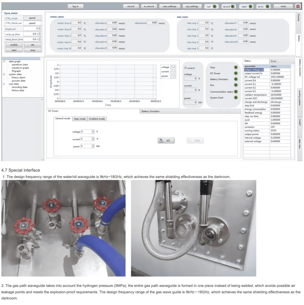
  • Monitoring software for real-time control and analysis

This comprehensive setup ensures that all necessary tests are conducted with high accuracy, helping you meet stringent EMC/EMI compliance standards for electric drives.

2. 主要技术指标

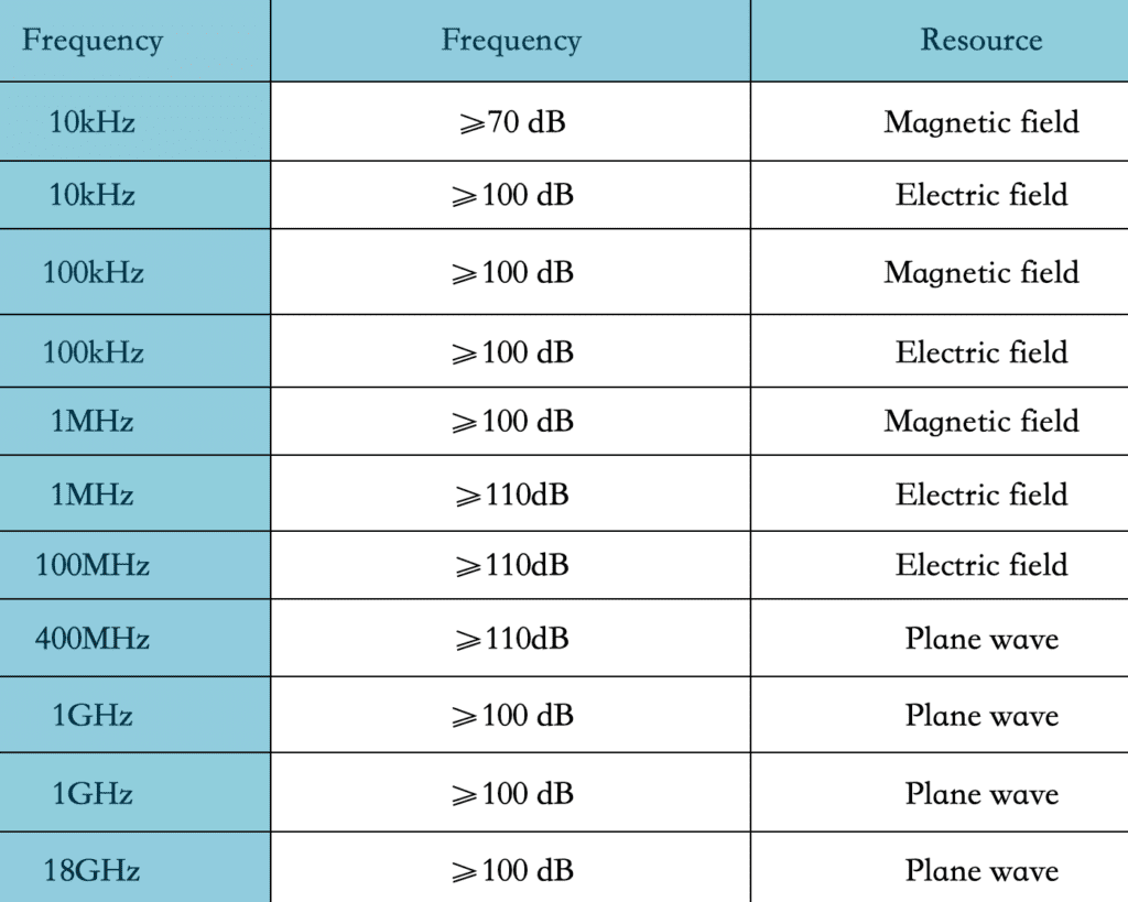
2.1 屏蔽效能-(东南欧) 电驱动EMC加载CISPR25暗室的屏蔽效能, 控制室, 功放室按照EN50147-1标准或最新GB/T12190标准执行 (频率范围10KHz~18GHz). 具体测试频率根据第三方检测机构的测试频率确定, 并满足以下指标:

安装所有相关配件后 (包括墙轴) 已完成, 电驱动EMC测功机工作原理 (可提供较小的无辐射负载), 和监控系统, 灯, 天线塔工作, 并且过滤器通电, 屏蔽效能水平比Class低至少10dB 5 限制 (PK&QP&的) CISPR25 指定.

2.2 测量控制精度 1) 扭矩测量精度: ±0.05%FS

2) 速度传感器脉冲分辨率: 1024/600ppppr

3) 扭矩控制精度: ±1%

4) 调速精度: ±0.01%满量程

5) 测功机最大振动速度值 (RSM): ≤2毫米/秒 (独立的), ≤3.5毫米/秒 (加载中)

6) 中间轴承座温升: ≤35℃

7) 中间轴承座最大振动速度值 (RSM): ≤2毫米/秒 (独立的), ≤3.5毫米/秒 (加载中)

2.3 长线法——(其他) 根据CISPR25最新版本, 模拟长线天线法 (其他) 采用频率范围150kHz~1GHz, 并且误差超过 90% 实际测试点与模型理论值相比不大于±6dB. 测试区域为电机侧和非电机侧. 测试邀请权威第三方计量机构进行测试并提供报告.

2.4 背景噪音-(荷兰银行) 当没有 DUT 时, 监控系统, 灯, 和过滤器通电, 9KHz~6GHz范围内, 测试背景噪声水平应至少低于本等级水平 5 限制 (PK&QP&的) 最新版CISPR25规定10dB, 比 GJB151B RE102 限值至少低 6dB. 本次测试邀请国家认可的第三方计量机构进行测试并提供报告.

2.5 无线电电波暗室建成后的空气质量, 具有CNAS、CMA资质的检验机构”HuaTest\” 应邀请进行暗室空气质量检测,并出具暗室空气质量检测结果 (至少含有甲醛, 苯, 甲苯, 二甲苯和TVOC) 报告, the test results meet the limit requirements of GB50325-2010 \”室内环境污染控制规定” 和国标 18883-2002 \”Indoor Air Quality Standards\”.

2.6 接地电阻 电波暗室、屏蔽室均采用单点接地, 接地电阻由我公司设计施工. 接地装置工艺采用物理降阻器, 但不使用耐化学性降低剂. 接地装置设计为可维护的. 暗室、屏蔽室接地电阻小于1Ω.

3. 执行标准

1. CISPR16-1-4 \”无线电干扰和抗扰度测试设备和方法部分规范 1-4: Radio Interference and Immunity Test Equipment Radiated Interference by Auxiliary Equipment\

2. CNAS-CL01-A008 \”测试和校准实验室能力标准在电磁兼容测试领域的应用说明”

3. EN50147 \Measurement method of shielding effectiveness of high-performance shielded room\

4. 国标/T 12190 \”Measurement Method of Shielding Effectiveness of Electromagnetic Shielding Room\

5. 国际标准化组织 4589-2 \”塑料 氧指数燃烧行为的测定 第一部分 2: Ambient-temperature test\

6. GB/T2406塑料燃烧性能试验方法氧指数法

7. 国标 8624 建筑材料及制品燃烧性能分级;

8. ISO 11452-1/-2/道路车辆-电子/电气元件抗窄带辐射电磁能的测试方法-无线电电波暗室法;

9. CISPR 25 \”车辆无线电骚扰特性的限值及测量方法, 用于保护车载接收器的船舶和内燃机”

10. MIL-STD-461G 子系统和设备电磁干扰特性控制要求

11.GJB 151B “军事设备和子系统电磁发射和灵敏度的要求和测量”

12.GBT 36282-2018 我”电动汽车驱动电机系统电磁兼容性要求及测试方法!”

13.国标 50325-2010 “土木建筑工程室内环境污染控制规范|”

14.GB/T18883-2002 \Indoor Air Quality\

4. Key technology description

The key technologies of the EMC test system for motors and drives include: 高速穿墙屏蔽轴系, 完整的电气隔离系统, 暗室无辐射传感器监测系统, 低噪声电池模拟器等系统, 实时监控系统等部分.

4.1 高速穿墙屏蔽轴系

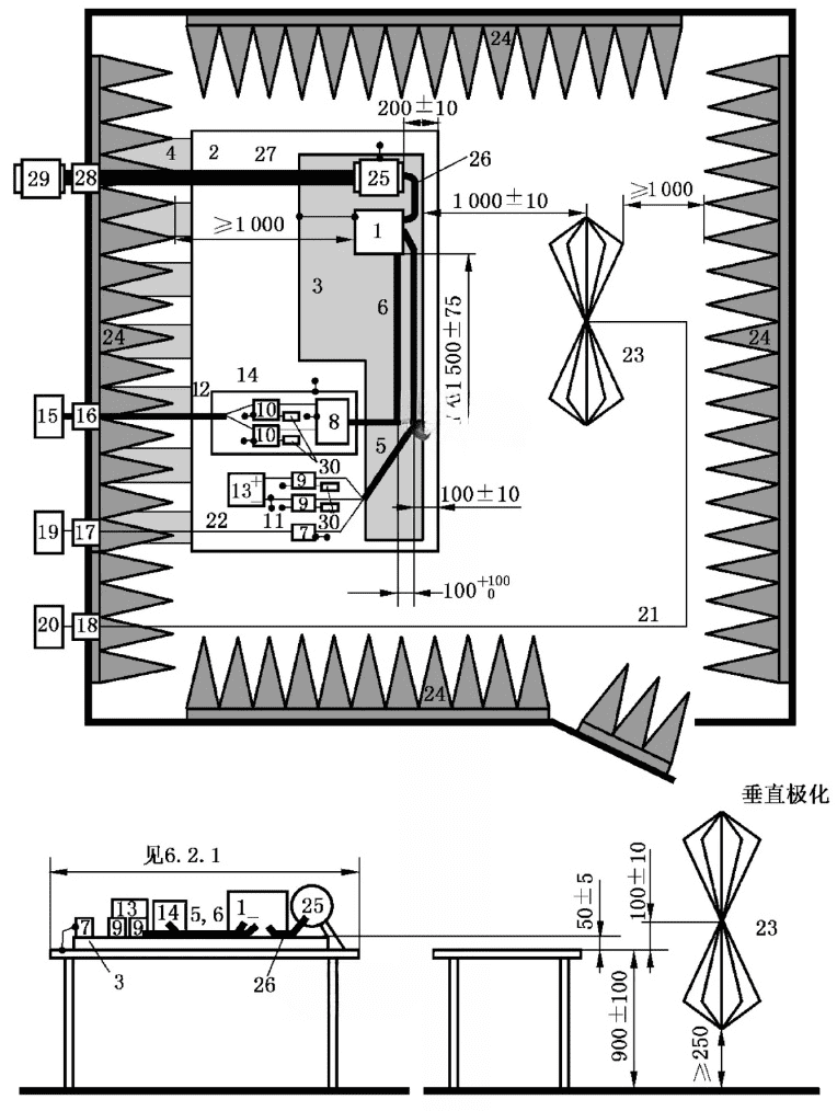
CISPR25 定义的测试布局

CISPR25标准明确要求控制器EUT与吸波材料中心的距离不小于1m. 用于三合一电驱动总成, 控制器内侧之间的距离 (靠近暗室一侧) 吸波材料顶部不小于1m, 电机驱动组件安装端距吸波材料顶部距离不小于1m. 为了满足这个要求, 轴系统的长度更长, 同时, 需要满足高速时振动较小的要求. 目前国外的解决方案是采用碳纤维轴或玻璃纤维轴, 测试条件要求轴的长度必须大于 1.6 米 (国际标准规定被测电机端面距电波暗室吸波材料顶部的距离不小于1m, 考虑吸波材料的厚度, 铁素体厚度, 和屏蔽层厚度, 同时还要考虑到安装过程中的错误). 虽然这两个非金属轴是不导电、无磁性的优良材料, 因为新能源汽车的电驱动系统已经进入高速大扭矩阶段, 玻璃纤维或碳纤维轴的绝对弹性模量不适合高速和高扭矩测试. 场景.

我公司设计的高速穿墙屏蔽井具有以下特点:

  1. 采用高精度低惯量刚性轴, 同时兼顾高速、大扭矩的特点.
  2. 作为电波暗室的一部分, 转轴具有良好的导电性, 从根本上屏蔽外界电磁辐射, 达到优异的屏蔽效果, 并减少暗室中的背景噪音.
  3. 通过可拆卸屏蔽盖, 测试电机可完全屏蔽, 并可独立测试驱动桥的电磁兼容特性.
EMC E-motor

为了满足高速, 同时满足大扭矩和屏蔽要求, 系统采用高精度长轴系统.

  1. 全速度范围内振动速度小于3.5mm/s.
  2. 轴系采用多点支撑结构, 便于暗室中底座对中,同轴度优于0.02mm.
  3. 轴系采用全动平衡结构, 动平衡精度达到G1级.
  4. 轴系一阶临界转速高于系统最高转速.

4.2 完全电气隔离的系统

为了防止电磁波和电荷从电波暗室外传导至电波暗室, 除了特殊的电磁屏蔽方法, 测功机必须完全电气隔离. 电驱动电机或动力总成需要满足单点接地要求.

  1. 测功机与屏蔽轴采用高速绝缘联轴器.
  2. 测功机与底座完全电气隔离.
  3. 高速屏蔽轴与被试电驱动电机轴采用高速绝缘联轴器.
  4. 电波暗室中的安装底座与电波暗室完全电气隔离.
  5. 电波暗室设计有可拆卸的完整屏蔽罩, 可以完全屏蔽电机并单独测试控制器的EUT.

4.3 暗室无辐射传感器监测系统

电波暗室中被测的电驱动系统和轴系统均设计有振动和温度监测传感器. 传感器需要通过高速数据采集系统采集并传输至监控软件进行信号分析和处理. 数据采集​​系统放置在电波暗室中. 由于其本身的辐射, 电波暗室的背景噪声会受到影响, 并且需要低噪声处理.

我公司对电波暗室数据采集系统做了以下设计:

  1. 数据采集​​系统电源经过24V滤波器滤波,消除进入电波暗室的电源干扰.
  2. 数据采集​​系统的信号传输设计. 实时以太网光纤转换器, 通过安装在电波暗室壁上的光纤和光纤波导, 将信号传输至电波暗室, 然后通过逆变器将其转换为数字信号, 并进入机器的上部位置.
  3. 数据采集​​系统安装在屏蔽箱内. 屏蔽箱内设计有通风波导,保证散热的同时保证箱内的电磁波不会传输到暗室.
  4. 传感器电缆采用专用屏蔽电缆, 将传感器和屏蔽盒连接成一个整体.

4.4 低噪声电池模拟器

电池模拟器为被测电机控制器供电, 可以模拟电池, 还可以进行电池组充放电测试.

1. 输出电压:

  • 最大输出电压 (六): 1200V
  • 输出电压范围: 20V~Unom可调, 设置分辨率: 0.1V
  • 重复性: ≤0.1% 六
  • 电压上升时间 (10% 到 90% 六): <5多发性硬化症 (阻性负载)
  • 负载变化 (10% 到 90%) 控制时间: ≤1ms (阻性负载)
  • 残余纹波: ≤0.2% Unom有效值 (频率 DC-1MHz)

2. 输出电流:

  • 最大输出电流 (之内): 800一个
  • 输出电流范围: 0~ 伊诺姆可调, 设置分辨率: 0.1一个
  • 重复性: ≤0.1%以内
  • 电流上升时间 (10% 到 90% 之内): <1多发性硬化症 (阻性负载)
  • 负载变化 (10% 到 90%) 控制时间: ≤1ms (阻性负载)
  • 温度系数: ≤0.01%以内/K
  • 残余纹波: ≤0.2% Inom有效值 (频率 DC-1MHz)
  1. 输出功率: ‡350kW
  2. 输出效率: >90%
  3. 输出精度: 0.1%
  4. 内阻:
  • 设定范围: 0~5W (调节分辨率0.1mW)
  • 电池模式: 通过调整内阻

电池模拟器的参数可根据实际需要定制.

4.5 实时监控系统

监控系统采用嵌入式实时控制器控制, 实时以太网通讯, 所有进入控制室的通讯电缆均通过光纤传输.

  1. 实时监测测功机前后轴承及温度, 实时监测测功机电流、电压, 并实时监测测功机的转速和扭矩.
  2. 屏蔽长轴振动实时监测.
  3. 实时监测被测电机的振动.
  4. 电控系统具有短路等保护功能, 泄漏, 停电, 过电流, 和过电压.
  5. 系统软件具有安全检测功能. 当监测值超过阈值时, 它会立即报警. 系统具有三级防护.
  6. 暗室采用无电磁辐射光电隔离数据采集系统, 实时采集振动传感器和温度传感器信号, 并通过光纤传输至控制室进行实时监控.
  7. 暗室测试台附近设计紧急停止按钮, 在控制室, 靠近测功机, ETC.
错误: 内容受到保护 !!