The growing complexity of modern propulsion systems is putting increasing pressure on instrumentation and testing systems. As key components such as internal combustion engines (ICE), hybrid engines, e-drives, and transmissions are developed simultaneously, it becomes critical to begin transmission testing as early as possible in the development cycle. Our solution is specifically designed to streamline the validation process for any type of transmission throughout its development stages.
With years of experience in developing transmission test systems for a wide variety of vehicles—including passenger cars, light-duty and heavy-duty trucks, buses, tractors, and off-road vehicles—we offer expert solutions that replace the original propulsion unit with a suitable AVL drive unit. These versatile test systems can be applied across numerous applications, such as durability testing, performance evaluations, functionality assessments, and NVH (Noise, Vibration, Harshness) analysis. Our solutions are built to address the demands of modern propulsion development, helping you manage the complexities of the validation process efficiently.

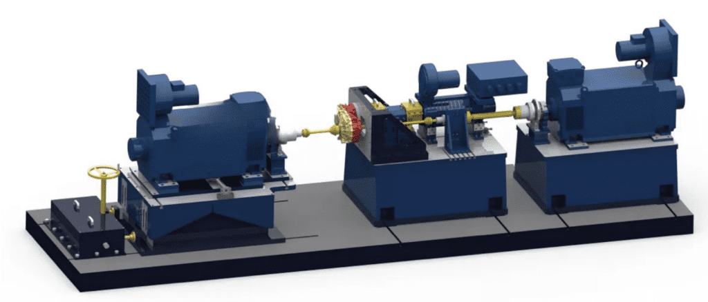
The high-speed reducer test bench is a comprehensive system designed to evaluate the performance of reducers used in electric and hybrid vehicles. It includes a low-inertia load analog dynamometer, a high-speed compact drive motor, a frequency converter, an environmental chamber, a cooling system, high-precision sensors, a vibration monitoring and early warning system, a mechanical system, and real-time control systems for both the dynamometer and the main control unit. The test bench operates through an advanced real-time dynamic control system, which adjusts speed and torque to simulate actual vehicle loads.
For electric drive powertrains, there is no need for high-speed drive motors; instead, low-inertia load simulation motors are used. The real-time controller ensures precise control of both speed and torque, simulating realistic load conditions. The main control system is integrated with the environmental chamber, power analyzer, cooling system, and equipment under test (EUT), enabling seamless control and monitoring. The data acquisition system collects data from various sensors—such as torque, vibration, temperature, and pressure sensors—and transmits it to the main control system. This data can then be displayed, stored, and processed via a software interface for further analysis.
This test system is primarily used for testing the reducers at the back end of high-speed motors in electric vehicles (EVs) or hybrid vehicles. It can simulate the onboard motor using a compact, high-speed drive motor with low inertia. The system also includes a load motor to simulate vehicle road load. For hybrid powertrain testing, two high-speed motors are typically used—one to simulate the onboard motor and one to simulate the engine—along with two load motors to replicate the vehicle load.
For a pure electric vehicle, the system typically uses one high-speed drive motor to simulate the onboard motor and two load motors to simulate the vehicle load. The high-speed reducer test bench is equipped with additional components like a battery simulator, power analyzer, and cooling system, which also allows for electric assembly testing.
The automobile transmission test bench is comprised of a drive motor and a loading motor. The drive motor simulates the input motor of an engine or an onboard motor in new energy vehicles, while the loading motor simulates the load experienced by the wheels of the vehicle. This combination allows for accurate and comprehensive testing of automotive transmission systems under a variety of conditions.
| Drive system selection: | |||||||
| Type | nmax(rpm) | Trated(N.m) | Prated(kW) | nrtated(rpm) | Pmax(kW)@nmax | Cooling | Inertia(kg.m2) |
| EC-A220-36 | 3000 | 3600 | 220 | 1001 | 220 | Air | 2.4 |
| EC-A250-30 | 3000 | 3000 | 250 | 795 | 250 | Air | 0.62 |
| EC-A250-40 | 3000 | 4000 | 250 | 597 | 250 | Air&Liquid | 0.8 |
| EC-B310-37 | 3300 | 3700 | 310 | 800 | 265 | Air | 6.3 |
| EC-B345-42 | 3000 | 4200 | 345 | 1107 | 310 | Air& | 3.5 |
| Load system selection: | |||||||
| Type | nmax(rpm) | Trated(N.m) | Prated(kW) | nrtated(rpm) | Pmax(kW)@nmax | Cooling | Inertia(kg.m2) |
| EC-A220-36 | 3000 | 3600 | 220 | 1001 | 220 | Air | 2.4 |
| EC-A250-30 | 3000 | 3000 | 250 | 795 | 250 | Air | 0.62 |
| EC-A250-40 | 3000 | 4000 | 250 | 597 | 250 | Air&Liquid | 0.8 |
| EC-B310-37 | 3300 | 3700 | 310 | 800 | 265 | Air | 6.3 |
| EC-B345-42 | 3000 | 4200 | 345 | 1107 | 310 | Air& | 3.5 |
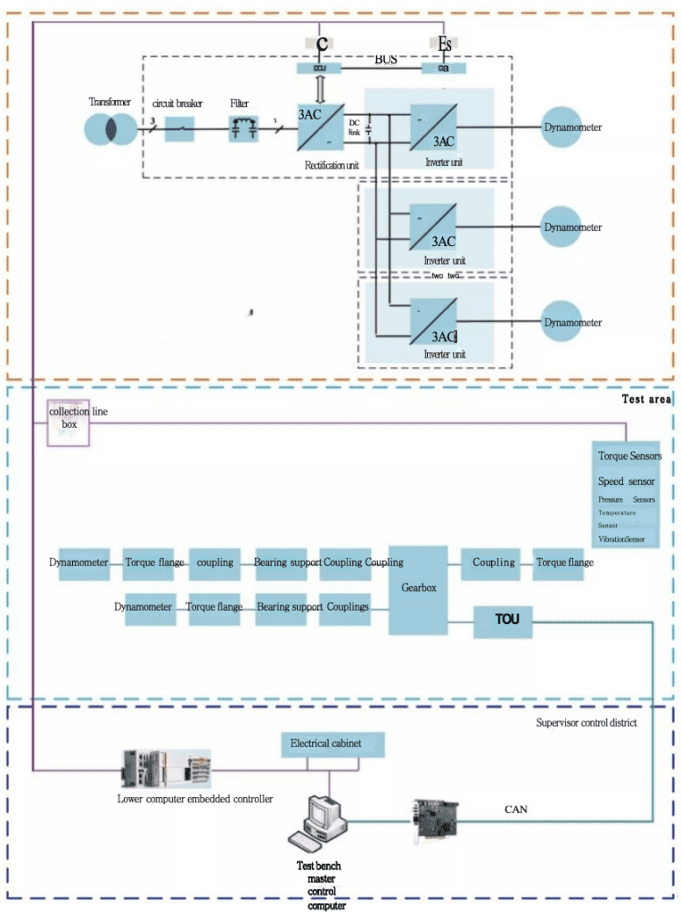
The test bench is divided into three primary zones: the Power Zone, the Test Zone, and the Monitoring Zone. Each zone is designed to handle specific tasks and components necessary for effective testing.
Power Zone: This area includes motor control inverters, electrical control cabinets, and associated power equipment. The inverter in this zone controls both the drive motor and the load motor of the dynamometer. The drive motor simulates the power source (such as a motor or engine) for the tested gearbox, while the load motor simulates road load conditions. When the drive motor is used for speed control, it typically operates in an electric mode, while the load motor functions as a generator. The energy generated by the load motor is fed back into the drive motor through the DC bus of the frequency converter, forming a closed electrical loop. In case of an emergency, the motor’s kinetic energy can be dissipated via a braking resistor. Both motors can be controlled in various ways, allowing flexible switching between drive control and load control as needed.
Test Zone: This zone is where the actual testing takes place. It is equipped with electric dynamometers, sensors, cooling systems for the dynamometer, the tested gearboxes, test benches, tooling, and shock-absorbing installation platforms. The dynamometer in this zone controls both speed and torque to simulate the vehicle’s road load. Different load simulation methods are available, including constant torque control, road spectrum input, calculated road spectrum, and user-defined load spectrum, allowing for a wide range of test conditions.
Monitoring Zone: The monitoring area is responsible for overseeing and controlling the entire test process. It is equipped with a main control computer, data acquisition systems, sensor signal processing systems, real-time controllers, and an operation console. The main control computer communicates with the dynamometer driver through Ethernet, enabling load simulation and real-time monitoring. The data acquisition system collects data from various sensors on-site and transmits it to the main control computer. The monitoring system then processes and displays this data, allowing for calculations and analysis. Additionally, vibration sensors continuously monitor the motor under test, the bearing housing of the test bench, and the dynamometer. If any abnormalities are detected, the main control system automatically halts the dynamometer and the motor under test, preventing further damage and recording the data leading up to the shutdown for future analysis. The main control system also includes four CAN bus interfaces for communication with the Transmission Control Unit (TCU) of the tested gearbox. A customizable CAN communication protocol is available, enabling users to tailor the system to their specific needs.
Additionally, the system includes an early fault diagnosis feature, which performs ongoing diagnostics and analysis of potential failures in the test piece. This includes detecting early signs of failure in rotating parts like gears and bearings, providing proactive warnings and analysis.
The three dynamometers within the system can be independently controlled, making it suitable for testing reducers. The system can also be configured to disconnect the drive-end dynamometer for powertrain testing by adding a battery simulator. Furthermore, it can be expanded into a four-power dynamometer setup, suitable for testing hybrid powertrains and hybrid reducers.
Torque Measurement Accuracy: ±0.05% FS to ±0.1% FS
Pulse Resolution of Speed Sensor: 1024/600 PPR (Pulses per Revolution)
Torque Control Accuracy: ±0.5% to ±1%
Speed Control Accuracy: ±0.01% FS
Maximum Vibration Speed of Dynamometer (RMS): ≤2 mm/s (independent), ≤3.5 mm/s (with loading)
Temperature Rise of Intermediate Bearing Seat: ≤35°C
Maximum Vibration Speed of Intermediate Bearing Seat (RMS): ≤2 mm/s (independent), ≤3.5 mm/s (with loading)
Test Motor Current Measurement Channels: 4/6 channels
Test Motor Voltage Measurement Channels: 4/6 channels
Power Analyzer Measurement Accuracy: ±(0.05%/0.1% of reading + 0.05%/0.1% of range)
Sampling Rate of Data Acquisition System: 1 kHz
User Data Acquisition System Channels: Optional
Temperature Measurement Range: -50°C to 200°C
Vibration Sensor Measuring Range (RMS): 0 to 20 mm/s
Overspeed Test
Testing the performance of the transmission or motor beyond normal operating speed.
Transmission Efficiency Test
Assessing the efficiency of the transmission under different operating conditions.
Differential Speed Performance Test
Evaluating the performance of differential mechanisms under various speeds.
Differential Reliability Test
Testing the long-term durability and reliability of the differential components.
Speed-Torque Characteristic Test
Measuring the torque and speed characteristics of the test unit to understand its performance profile.
Powertrain Efficiency Test
Efficiency testing for electric or hybrid vehicle powertrains (including efficiency mapping). Supports DC bidirectional power supply and power analyzer.
Speed Control Accuracy Test
Testing the ability of an electric or hybrid powertrain to maintain precise speed control.
Torque Control Accuracy Test
Evaluating the accuracy of torque control in electric or hybrid powertrains.
Speed Response Time Test
Measuring the response time of the powertrain to changes in speed, relevant for electric or hybrid systems.
Torque Response Time Test
Testing the powertrain’s response time to torque variations in electric or hybrid powertrains.
Accelerated Performance Test
Testing the powertrain or transmission under accelerated load conditions to simulate real-world performance.
Electric Working Condition Test
Simulating working conditions for the electric drivetrain using a DC bidirectional power supply and power analyzer for hybrid or electric powertrains.
Power Generation Condition Test
Testing the power generation capabilities of a drivetrain under various conditions using a DC bidirectional power supply and power analyzer for hybrid or electric powertrains.
Vibration Detection
Monitoring and analyzing vibration levels during tests to ensure that components are functioning within acceptable limits.
Noise Detection
Detecting and measuring noise generated by the drivetrain or components to ensure compliance with noise standards.
Road Spectrum Simulation Test
Simulating real-world road conditions by applying a road spectrum load to the drivetrain for performance evaluation.
Fatigue Test
Performing extended duration tests to assess the fatigue resistance of components and systems under continuous operation.
Dynamic Tightness Test
Testing for dynamic tightness, ensuring that components and systems maintain proper sealing during operation.
Test Bench Detection Objects
The test bench is designed to test reducers for pure electric passenger cars with a rated input power of no greater than 250 kW, as well as various passenger car automatic transmissions, such as AT (Automatic Transmission), DCT (Dual-Clutch Transmission), AMT (Automated Manual Transmission), and CVT (Continuously Variable Transmission).
The drive motor on the test bench is a high-speed, low-inertia motor designed with a compact center height, as low as 132mm, making it suitable for a wide range of transmission input and output shaft spacings. This motor can meet the majority of testing requirements across various applications.
The loading dynamometer uses either a low-inertia synchronous motor or an asynchronous motor, with a recommendation to select a very low-inertia synchronous motor for tests that require high dynamics. The dynamometer’s design incorporates vibration monitoring on both the front and rear bearing sides, ensuring stability and precision. Additionally, the motor’s three-phase windings and bearings are equipped with temperature monitoring, ensuring the system operates within safe and optimal temperature limits.
The motor test bench is equipped with an embedded real-time controller for managing the entire monitoring system. The system employs EtherCAT communication to enable high-speed, dynamic control. This advanced setup allows for a no-load dynamic response time of under 10ms, making it capable of handling complex variable test conditions with remarkable accuracy and speed. The system’s real-time control ensures that the motor and dynamometer work seamlessly, even under rapidly changing testing parameters.
The mechanical components of the test bench are produced using high-precision machining centers, ensuring extremely tight tolerances and high machining accuracy. The shaft coaxiality is maintained to better than 0.02mm, which ensures that all rotating parts are perfectly aligned, minimizing vibration and maximizing the precision of test results. This level of accuracy is essential for high-performance motor and drivetrain testing.
The high-speed bearing support uses high-speed angular contact ball bearings that are spring-preloaded, ensuring stable operation under high-speed conditions. The temperature rise of these bearings does not exceed 35°C, ensuring long-term reliability and minimizing wear. At the highest speeds, the vibration speed remains below 2.5mm/s (RMS), indicating exceptional smoothness in operation. The bearings are grease-lubricated and maintenance-free, designed to run continuously for up to 20,000 hours without requiring servicing, contributing to the overall durability and low maintenance requirements of the test bench.
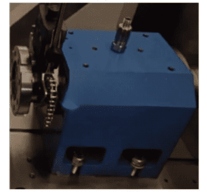
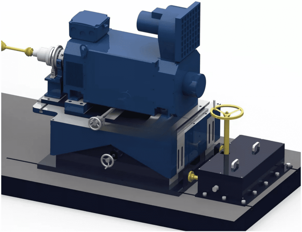
To accommodate a wide range of test setups and configurations, the motor test bench includes adjustable spatial positions for both the drive motor and the loading dynamometer.
Drive Motor Position Adjustment:
Adjustment Direction: Height
Adjustment Range: +50mm
Adjustment Method: Manual
Locking Method: Bolt locking
Load Dynamometer Position Adjustment:
Adjustment Direction: Height
Adjustment Range: ≥100mm
Adjustment Direction (Horizontal Axis): ≥200mm
Adjustment Range (Radial): ≥80mm
Adjustment Method: Manual
Locking Method: Bolt locking
These adjustable positions provide flexibility, allowing for optimal alignment of the motor and dynamometer to suit the specific test requirements and ensure accurate measurements during tests.
4.6 Perfect safety protection measures
4.7 Complete monitoring software
The motor test bench software adopts a modular design architecture. Users can customize the test process and working condition parameters to realize the control of the motor speed and torque. The system classifies users and opens different functional modules. The system has the function of automatic zero point calibration at startup. The software has a dedicated sensor calibration module, and users can calibrate the sensor regularly. The communication interface with EUT is reserved to realize the control of EUT. It has the following functions:
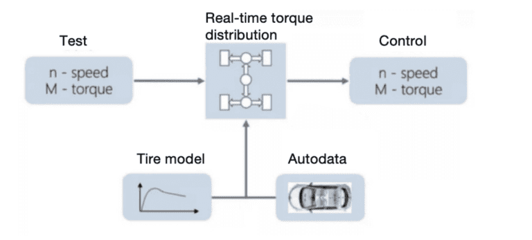
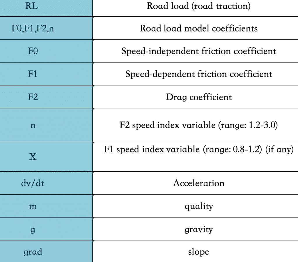
The vehicle road simulation function is integrated in the real-time controller. The vehicle road simulation function is used to realize the road resistance, slope resistance simulation and inertia simulation of the vehicle on the bench. These resistance simulations can be expressed by the following formula:

For any questions or support, please reach out via email at [email protected].
We aim to respond promptly.
Need immediate assistance? Call us at +86 156 1877 0706.
Our team is ready to assist you.
We welcome you to visit our office located at 3F, Building 2, NO.511 Xiaowan Road, Fengxian, Shanghai, China.
Let's discuss your needs in person.

© 2025 Shanghai EconoTechnology Co., Ltd. All rights reserved.
Empowering innovation through reliable testing solutions.