

We offer fully engineered, bespoke test bench solutions designed to meet the specific needs of the automotive sector
Our Dynamometers cover a wide range of Torque, Speed and Mechanical Power ratings.

A Motor test bench is essentially a controlled environment that allows engineers and developers to test and evaluate systems

We provide the torquemeters, couplings, flywheels, spindles & test rigs for both helicopter and aero engine component testing

We provide test solution for marine engines, propulsion systems, electric motors, generator sets, transmission gearboxes, auxiliary power systems, exhaust gas systems, and spare parts for ships
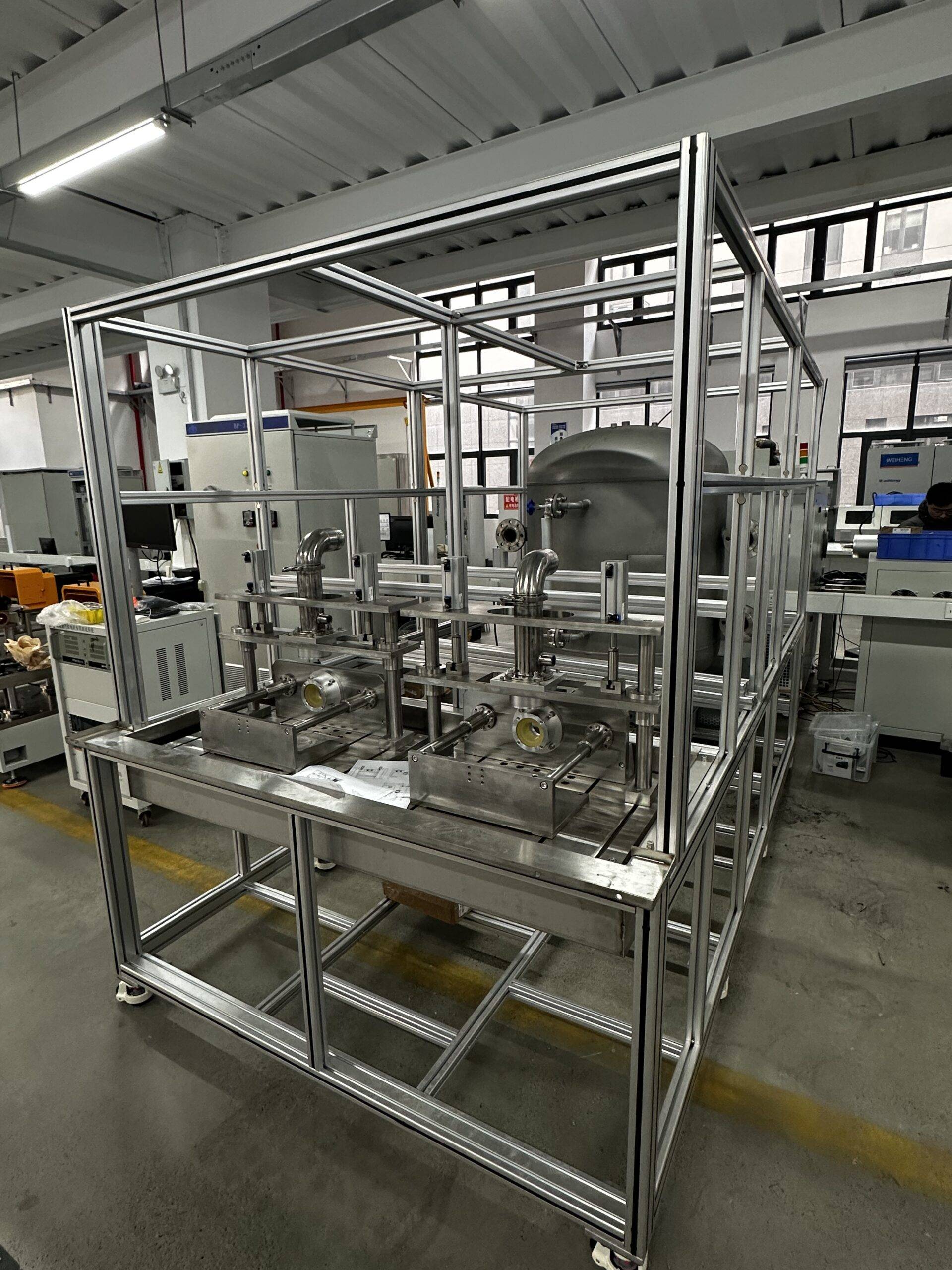
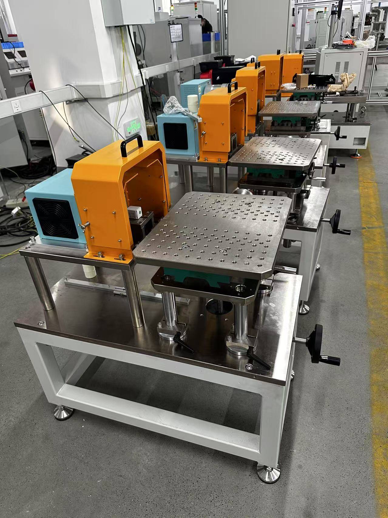
Water pump testing system is a specialized equipment used for performance testing of water pumps, commonly used to assess key parameters such as flow, head, power, and efficiency.

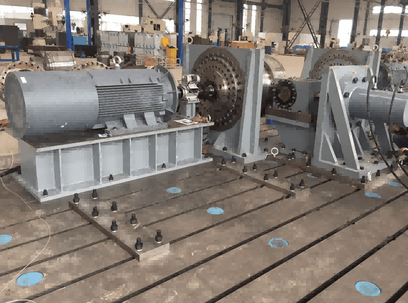
The high-speed motor test bench is a specialized system designed to evaluate and validate the performance of high-speed electric motors under various operating conditions. It consists of several key components, including a dynamometer, real-time controller, data acquisition system, and various sensors
Planetary Reducer Test Bench, Harmonic Reducer Test Bench RV Reducer Test Bench Four-Series Reducer Test Benches
![]()
![]()
© 2025 Shanghai EconoTechnology Co., Ltd. All rights reserved.
Empowering innovation through reliable testing solutions.