Products

E-motor EMC testing solution

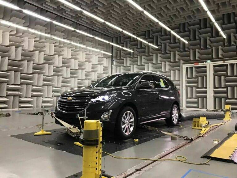
Our e-motor EMC testing solution are tailored to meet the growing demands for compliance and performance testing across industries such as automotive, marine, and aerospace. These solutions are both cost-effective and efficient, ensuring consistent and repeatable test results across a variety of setups and configurations.

We offer full vehicle test setups equipped with multi-axle chassis load machines, four-wheel drive capabilities, fully automated remote antenna positioning, and specialized charging mode test configurations. This flexibility makes our solutions ideal for testing not only complete vehicles but also Electric or Electronic Sub-Assemblies (ESA), covering a wide range of applications.

One standout feature of our load machines is the conventional through-shaft EMC chamber installation, designed to meet the CISPR 25 standard. This installation is perfect for testing e-motors ranging from smaller 20 kW units found in motorcycles to larger 700 kW systems commonly used in commercial vehicles. It ensures a thorough evaluation of all dynamic e-motor requirements, helping to accurately assess performance characteristics.

For situations where a permanent load machine installation isn’t feasible, we provide mobile testing equipment as a flexible alternative. This mobile setup can be used in multi-purpose or existing EMC chambers, offering the same comprehensive capabilities and functionality as our stationary systems, though with a slightly limited power capacity range.

Our solutions are designed to ensure you can meet the highest standards of performance and compliance, all while maintaining flexibility and cost-efficiency for your testing needs.

1.E-motor EMC testing solution: Direct drive connection testing type

The direct drive system is designed for performing precise EMC/EMI tests on high-speed motors and controllers. This system is ideal for testing both separate motors and controllers, as well as integrated motor-controller units.

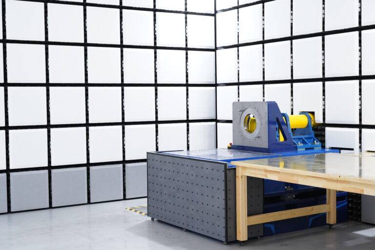
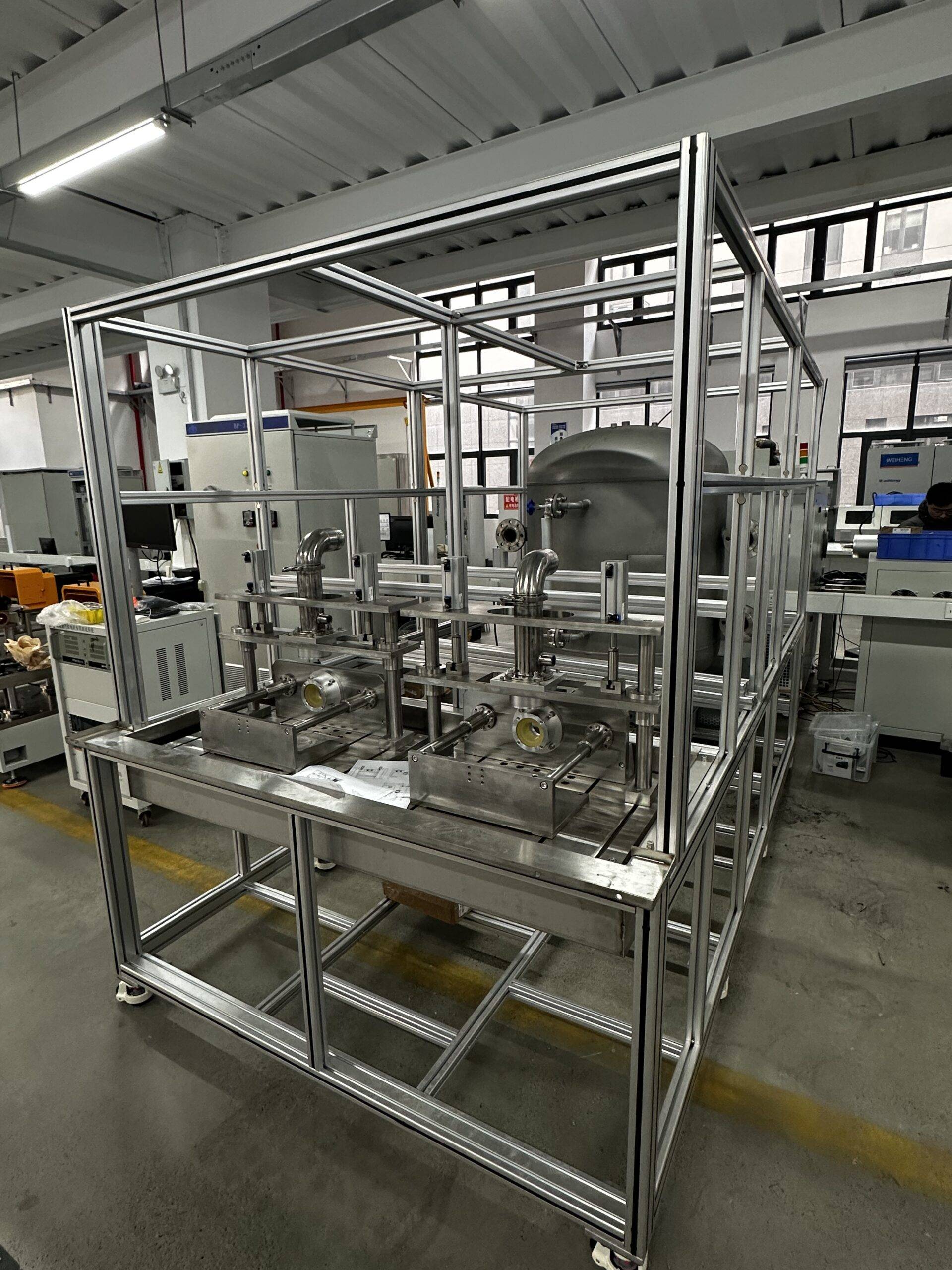
In the setup, high-speed motors are mounted on the end face of an L-shaped tooling or T-slot platform, while the controller is placed securely on the test table. This versatile configuration allows for thorough testing of individual components or integrated systems.

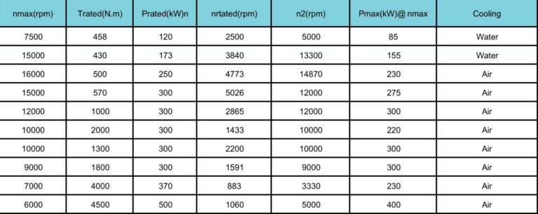
The system can be customized to match the specific parameters of the motor being tested. Depending on the motor’s size and requirements, the appropriate dynamometer can be selected. Below are the recommended dynamometer parameters for optimal testing performance:

All the parameters can be customized depends on the requirement, the solution can be integrated with gearbox in order to output more torque.

2.E-motor EMC testing solution: Mobile/ Portable e-motor EMC testing

EMC

The mobile portable e-motor EMC testing solution is an innovative addition to our comprehensive range of load machine options for electric vehicle (EV) component EMC testing. This mobile setup features an EMC load machine with advanced drive electronics and controls, all contained within a shielded, free-standing mobile unit.

The system supports full four-quadrant (4Q) operation, allowing for testing of both the e-motor drive and regenerative functions. It is designed to meet all current emission and immunity standards, ensuring the highest quality of the testing environment with no compromises.

Key Advantages:

One of the standout benefits of this mobile e-motor EMC testing solution is its flexibility. It can be used in existing EMC chambers typically designed for testing consumer electronics or complete vehicles, which means minimal adjustments to the testing environment. This makes it an economical solution for manufacturers looking to streamline their testing procedures.

Many of these chambers already come equipped with essential features like turntables and raised flooring, which facilitate the routing of signal fiber optics and power cables beneath the floor. These built-in features help simplify the setup process and enhance overall operational efficiency.

Streamlined Testing Process:

To maximize efficiency, the Unit Under Test (UUT) can be prepared on the mobile load machine outside the EMC chamber. Once the setup is ready, it can be easily transferred into the chamber using a standard pallet truck, and quickly connected to the power supply. This simple transfer process reduces downtime and ensures more testing time.

Modular and Customizable:

The modular design of the mobile testing platform allows for customization based on specific needs. For instance, if higher speed or torque testing is required, a larger and more capable e-motor and drive unit can be added. This flexibility ensures the mobile solution evolves with the growing demands of manufacturers and researchers, providing a versatile platform for comprehensive EMC testing of e-motor components.

In essence, the mobile e-motor EMC testing solution offers a cost-effective, efficient, and flexible approach to testing that can meet the complex needs of the evolving electric vehicle industry.

3.E-motor EMC testing solution: Two-Axis EMC Loading Testing System

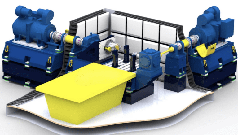
The two-axis loading dynamometer system is designed to closely replicate the real-world installation of a vehicle powertrain, offering a highly accurate simulation. This system ensures that the differential is neither locked nor welded, and the output shafts on both sides of the powertrain can be swapped out for on-board half shafts. Additionally, the wheel spacing can be adjusted to match the actual vehicle specifications, providing a realistic testing environment.

This system is particularly well-suited for EMC testing of passenger car motors, with capabilities that include a maximum speed of 12,000 rpm and a rated torque of 1000 N·m. One of its key features is the ability to design the semi-axles on both sides of the powertrain to be insulated from the ground, effectively simulating the behavior of vehicle tires during testing.

For high-speed motor testing, the low-speed shaft side shafting system can be easily removed to facilitate testing of faster motors. Additionally, for scenarios where space is limited in the EMC test chamber, a right-angle transmission box can be used to optimize space and maintain functionality.

This versatile system offers the flexibility to meet a wide range of testing needs, making it an ideal solution for testing e-motors and powertrains in realistic conditions while ensuring accurate EMC/EMI performance evaluation.

4.E-motor EMC testing solution: Powertrain EMC Testing System

Our electric drive and powertrain universal dynamometers are designed to handle a variety of testing needs, including EMC/EMI testing for high-speed motors, low-speed high-torque powertrains, and low-speed high-torque motors. This versatile system is perfect for evaluating the full range of electric drive systems under real-world conditions.

The system utilizes a medium-speed high-torque dynamometer that connects to a dual-output shaft gearbox. Through gear transmission, the high-speed shaft can be increased to higher speeds, while the low-speed shaft is directly powered by the dynamometer. This flexible configuration allows for testing both high-speed, low-torque and low-speed, high-torque electric drive systems.

However, due to the introduction of a high-speed gearbox, the mounting surface area for the motor will be larger, and the reflecting surface area will also increase. This can lead to a slight impact on measurement uncertainty. To mitigate these effects, our product is equipped with several key design features to ensure optimal performance and accuracy:

  1. Oil and Gas Absorption Device: The high-speed gearbox is equipped with a device that prevents oil and gas from volatilizing into the anechoic chamber, maintaining the integrity of the testing environment.

  2. Medium-Speed High-Torque Dynamometer: This dynamometer reduces the gearbox’s transmission ratio, lowers the center distance, and minimizes the gearbox’s cross-sectional area. This design effectively reduces the impact on measurement uncertainty, ensuring more precise test results.

  3. Lubrication System with Power-Failure Protection: The gearbox’s lubrication system is equipped with a mechanism that continues to supply oil for at least 5 minutes after a power failure, preventing damage to the gearbox due to oil cutoff during testing.

  4. Constant Temperature Lubrication System: The system features a constant temperature device that ensures the oil inlet temperature remains stable. This helps minimize the influence of lubricating oil viscosity on transmission efficiency and eliminates errors in torque measurement caused by fluctuations in transmission efficiency.

These thoughtful design elements ensure that our powertrain testing system delivers accurate and reliable results, even in complex testing scenarios. The system is highly adaptable and capable of addressing a wide variety of electric drive and powertrain testing requirements

EMC

Technical description-1. System Architecture of E-motor EMC testing solution

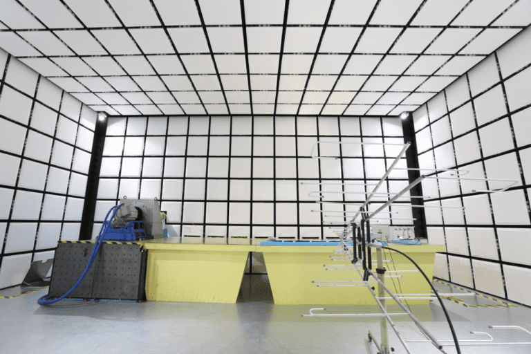
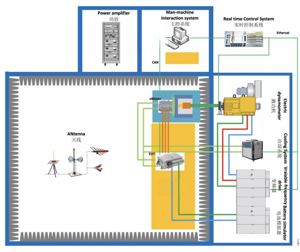
The electric drive EMC/EMI test system typically consists of an electric wave anechoic chamber, a dynamometer system, and various measuring instruments. We primarily offer the anechoic chamber and dynamometer system.

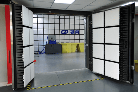
The anechoic chamber is typically a standard CISPR25 chamber, designed to ensure accurate testing in controlled conditions. The dynamometer system, on the other hand, is customized based on the specifications of the product being tested. It generally includes several key components, such as:

  • A power dynamometer to simulate the load

  • A through-wall shielding shaft system for precise measurements

  • An installation stand for secure positioning

  • A frequency converter to adjust operational parameters

  • A battery simulator to mimic real-world energy sources

  • A cooling system to regulate temperature during tests

  • A sensor measurement system to capture critical data

  • A data acquisition system for processing and recording results

  • Monitoring software for real-time control and analysis

This comprehensive setup ensures that all necessary tests are conducted with high accuracy, helping you meet stringent EMC/EMI compliance standards for electric drives.

2. Key technical indicators

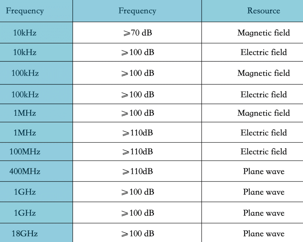
2.1 Shielding effectiveness-(SE) The shielding effectiveness of the electric drive EMC loading CISPR25 darkroom, control room, and power amplifier room is implemented in accordance with the standard EN50147-1 or the latest GB/T12190 standard (frequency range 10KHz~18GHz). The specific test frequency is determined according to the test frequency of the third-party testing agency, and meets the following indicators:

After the installation of all relevant accessories (including the wall shaft) is completed, the electric drive EMC dynamometer works (small non-radiation load can be provided), and the monitoring system, lamps, antenna tower work, and the filter are energized, the shielding effectiveness The level is at least 10dB lower than the Class 5 limit (PK&QP&AV) specified by CISPR25.

2.2 Measurement control accuracy 1) Torque measurement accuracy: ±0.05%FS

2) Pulse resolution of speed sensor: 1024/600pprppr

3) Torque control accuracy: ±1%

4) Speed control accuracy: ±0.01%FS

5) The maximum vibration speed value of the dynamometer (RSM): ≤2mm/s (independent), ≤3.5mm/s (loading)

6) Temperature rise of intermediate bearing seat: ≤35℃

7) The maximum vibration speed value of the intermediate bearing seat (RSM): ≤2mm/s (independent), ≤3.5mm/s (loading)

2.3 Long-line method-(LWM) According to the latest version of CISPR25, the Modelled long wire antenna method (LWM) is adopted in the frequency range of 150kHz~1GHz, and the error of more than 90% of the actual test points is not more than ±6dB compared with the theoretical value of the model. The test area is the motor side and the non-motor side. The test invites an authoritative third-party measurement agency to conduct the test and provide a report. 

2.4 Background noise-(ABN) When there is no DUT, monitoring system, lamps, and filters are energized, in the range of 9KHz~6GHz, the test background noise level should be at least lower than the level of the Class 5 limit (PK&QP&AV) specified in the latest version of CISPR25 10dB, which is at least 6dB lower than the GJB151B RE102 limit. This test invites third-party measurement institutions certified by the state to conduct tests and provide reports. 

2.5 Air quality After the construction of the radio anechoic chamber is completed, an inspection agency with CNAS and CMA qualification \”HuaTest\” shall be invited to conduct air quality testing in the darkroom and issue a test for the air quality in the darkroom (including at least formaldehyde, benzene, toluene, dimethylbenzene and TVOC) Report, the test results meet the limit requirements of GB50325-2010 \”Indoor Environmental Pollution Control Regulations\” and GB/T 18883-2002 \”Indoor Air Quality Standards\”. 

2.6 Grounding resistance The anechoic chamber and shielding room are grounded by single-point grounding, and the grounding resistance is designed and constructed by us. The grounding device process uses physical resistance reducers, but does not use chemical resistance reducers. The grounding device is designed to be maintainable. The grounding resistance of dark room and shielded room is less than 1Ω.

3. Implementation standards 

1. CISPR16-1-4 \”Specifications for Radio Interference and Immunity Test Equipment and Methods Part 1-4: Radio Interference and Immunity Test Equipment Radiated Interference by Auxiliary Equipment\” 

2. CNAS-CL01-A008 \”Instructions for the Application of Testing and Calibration Laboratory Competence Criteria in the Field of Electromagnetic Compatibility Testing\” 

3. EN50147 \”Measurement method of shielding effectiveness of high-performance shielded room\” 

4. GB/T 12190 \”Measurement Method of Shielding Effectiveness of Electromagnetic Shielding Room\” 

5. ISO 4589-2 \”Plastics-Determination of burning behaviour by oxygen index Part 2: Ambient-temperature test\” 

6. GB/T2406 Plastic Combustion Performance Test Method Oxygen Index Method 

7. GB 8624 Classification of burning performance of building materials and products; 

8. ISO 11452-1/-2/Road vehicles-Test methods for immunity of electronic/electrical components to narrowband radiated electromagnetic energy-Radio anechoic chamber method; 

9. CISPR 25 \”Limits and Measurement Methods of Radio Disturbance Characteristics of Vehicles, Ships and Internal Combustion Engines Used to Protect Vehicle-mounted Receivers\” 

10. MIL-STD-461G REQUIREMENTS FOR THE CONTROL OF ELECTROMAGNETIC INTERFERENCE CHARACTERISTICS OF SUBSYSTEMS AND EQUIPMEN

11.GJB 151B “Requirements and Measurements for Electromagnetic Emission and Sensitivity of Military Equipment and Subsystemsl”

12.GBT 36282-2018 l”Electric Vehicle Drive Motor System Electromagnetic Compatibility Requirements and Test Methods!”

13.GB 50325-2010 “Code for Indoor Environmental Pollution Control of Civil Construction Engineering|”

14.GB/T18883-2002 \”Indoor Air Quality\”

4. Key technology description

The key technologies of the EMC test system for motors and drives include: high-speed wall-through shielding shafting, complete electrical isolation system, dark room non-radiation sensor monitoring system, low-noise battery simulator and other systems, real-time monitoring system and other parts. 

4.1 High-speed through-wall shielding shafting

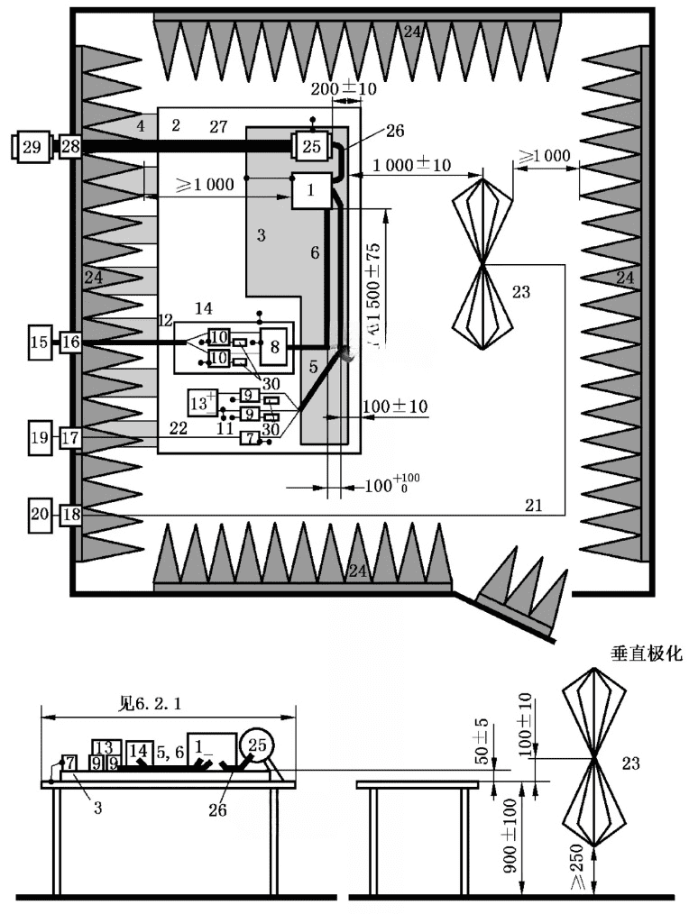
CISPR25 defined test layout

The CISPR25 standard clearly requires that the distance between the controller EUT and the center of the absorbing material is not less than 1m. For the three-in-one electric drive assembly, the distance between the inner side of the controller (near the darkroom side) and the top of the absorbing material is not less than 1m, and the distance between the mounting end of the motor drive assembly and the top of the absorbing material is not less than 1m. In order to meet this requirement, the length of the shaft system is longer, and at the same time, it needs to meet the requirement of less vibration at high speed. The current foreign solution is to use carbon fiber shaft or glass fiber shaft, the test conditions require that the length of the shaft must be greater than 1.6 meters (international standards stipulate that the distance between the end face of the motor under test and the top of the anechoic chamber absorbing material is not less than 1m, considering the absorbing material Thickness, ferrite thickness, and shield thickness, while also taking into account the error during installation). Although these two non-metallic shafts are excellent materials that are non-conductive and non-magnetic, because the electric drive system of new energy vehicles has entered the stage of high-speed and high-torque, the absolute elastic modulus of glass fiber or carbon fiber shafts is not suitable for high-speed and high-torque testing. Scenes.

The high-speed through-wall shielding shaft designed by our company has the following characteristics:

  1. Adopt high-precision and low-inertia rigid shaft, while taking into account the characteristics of high speed and large torque.
  2. As a part of the anechoic chamber, the rotating shaft has good conductivity, fundamentally shields external electromagnetic radiation, achieves an excellent shielding effect, and reduces background noise in the darkroom.
  3. Through the detachable shielding cover, the test motor can be completely shielded, and the electromagnetic compatibility characteristics of the drive axle can be tested independently.
EMC E-motor

In order to meet the high-speed, large-torque and shielding requirements at the same time, the system adopts a high-precision long-axis system.

  1. The vibration speed in the full speed range is less than 3.5mm/s.
  2. The shaft system adopts a multi-point support structure, which is convenient for centering the base in the dark room and the coaxiality is better than 0.02mm.
  3. The shaft system has a fully dynamic balance structure, and the dynamic balance accuracy reaches G1.
  4. The first-order critical speed of the shaft system is higher than the maximum speed of the system.

4.2 Completely electrically isolated system

In order to prevent electromagnetic waves and charges from being conducted outside the anechoic chamber to the anechoic chamber, in addition to special electromagnetic shielding methods, the dynamometer must be completely electrically isolated. Electric drive motors or powertrains need to meet single-point grounding requirements.

  1. The dynamometer and the shielded shaft adopt high-speed insulation coupling.
  2. The dynamometer is completely electrically isolated from the base.
  3. The high-speed shielded shaft and the tested electric drive motor shaft adopt high-speed insulation coupling.
  4. The installation base in the anechoic chamber is completely electrically isolated from the anechoic chamber.
  5. The anechoic chamber is designed with a removable complete shielding cover, which can completely shield the motor and test the EUT of the controller individually.

4.3 Non-radiation sensor monitoring system in dark room

The electric drive system and shaft system under test in the anechoic chamber are all designed with vibration and temperature monitoring sensors. The sensors need to be collected by a high-speed data acquisition system and transmitted to the monitoring software for signal analysis and processing. The data acquisition system is placed in the anechoic chamber. Due to its own radiation, the background noise of the anechoic chamber will be affected, and low noise processing is required.

Our company has made the following designs for the data acquisition system in the anechoic chamber:

  1. The power supply of the data acquisition system is filtered by a 24V filter to eliminate the power interference entering the electric wave dark room.
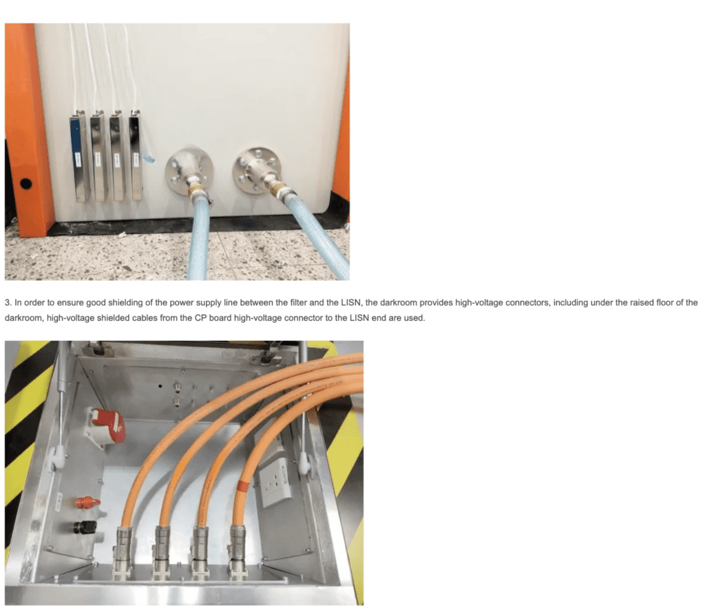
  2. The signal transmission design of the data acquisition system. Real-time Ethernet optical fiber converter, through optical fiber and optical fiber waveguide installed on the wall of the anechoic chamber, transmits the signal to the anechoic chamber, and then converts it into a digital signal through an inverse converter, and enters the upper position In the machine.
  3. The data acquisition system is installed in a shielded box. The shielded box is designed with ventilation waveguides to ensure heat dissipation and at the same time ensure that the electromagnetic waves in the box will not be transmitted to the dark room.
  4. The sensor cable adopts a special shielded cable, which connects the sensor and the shielded box as a whole.

4.4 Low noise battery simulator

The battery simulator supplies power to the motor controller under test, can simulate the battery, and can also perform battery pack charge and discharge tests.

1. Output voltage:

  • Maximum output voltage (Unom): 1200V
  • Output voltage range: 20V~ Unom adjustable, setting resolution: 0.1V
  • Repeatability: ≤0.1% Unom
  • Voltage rise time (10% to 90% Unom): <5ms (resistive load)
  • Load change (10% to 90%) control time: ≤1ms (resistive load)
  • Residual ripple: ≤0.2% Unom effective value (frequency DC-1MHz)

2. Output current:

  • Maximum output current (Inom): 800A
  • Output current range: 0~ Inom adjustable, setting resolution: 0.1A
  • Repeatability: ≤0.1% Inom
  • Current rise time (10% to 90% Inom): <1ms (resistive load)
  • Load change (10% to 90%) control time: ≤1ms (resistive load)
  • Temperature coefficient: ≤0.01% Inom/K
  • Residual ripple: ≤0.2% Inom effective value (frequency DC-1MHz)
  1. Output power: ‡350kW
  2. Output efficiency: >90%
  3. Output accuracy: 0.1%
  4. Internal resistance:
  • Setting range: 0~ 5W (adjustment resolution 0.1mW)
  • Battery mode: by adjusting internal resistance

The parameters of the battery simulator can be customized according to actual needs.

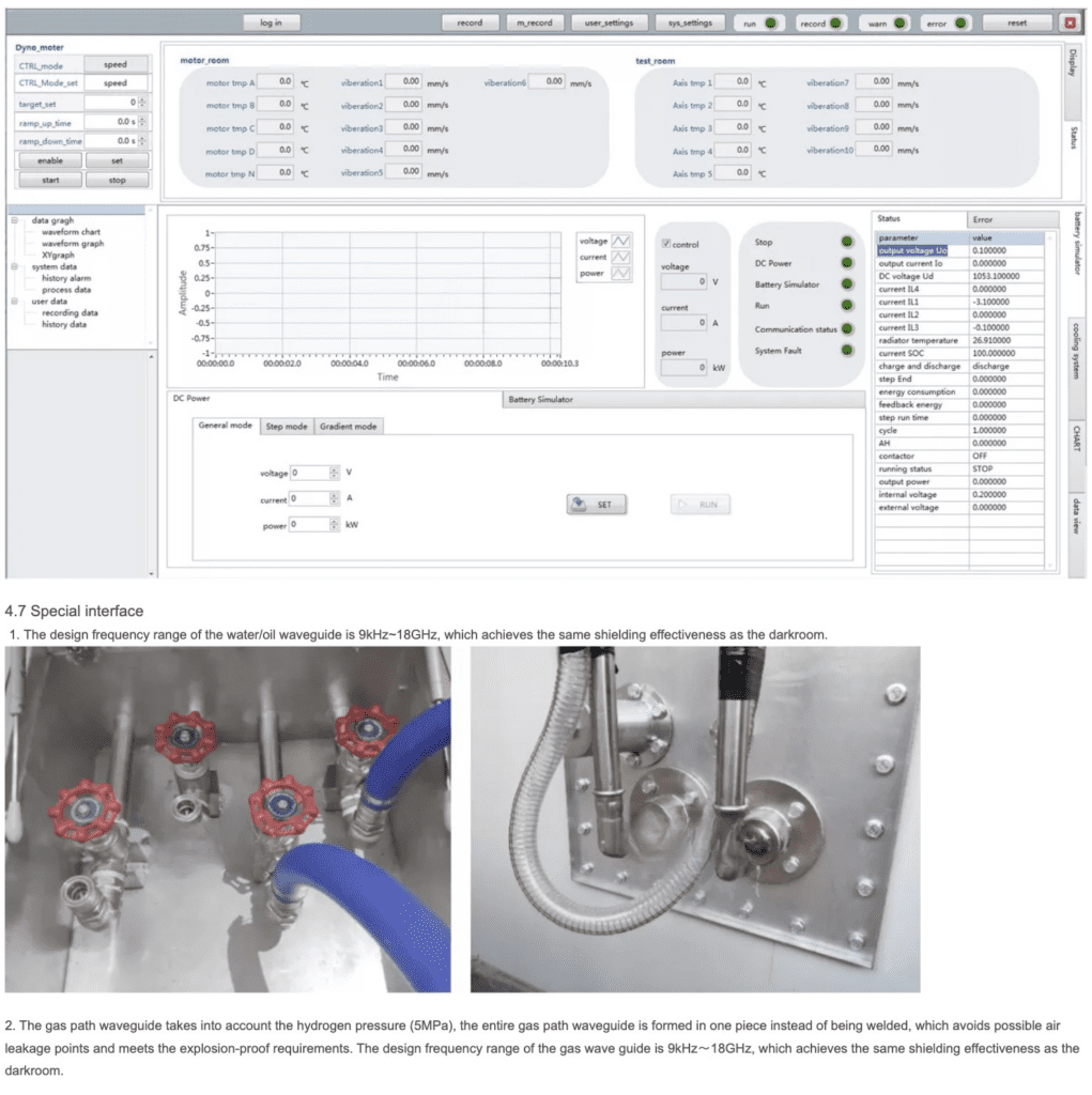
4.5 Real-time monitoring system

The monitoring system adopts embedded real-time controller control, real-time Ethernet communication, and all communication cables entering the control room are transmitted through optical fibers.

  1. Real-time monitoring of the front and rear bearings and temperature of the dynamometer, real-time monitoring of the current and voltage of the dynamometer, and real-time monitoring of the speed and torque of the dynamometer.
  2. Shield the real-time monitoring of the vibration of the long axis.
  3. Real-time monitoring of the vibration of the motor under test.
  4. The electronic control system has protection functions such as short circuit, leakage, power failure, overcurrent, and overvoltage.
  5. The system software has a safety detection function. When the monitoring value exceeds the threshold, it will immediately alarm. The system has three levels of protection.
  6. The dark room adopts a non-electromagnetic radiation photoelectric isolation data acquisition system, which collects vibration sensor and temperature sensor signals in real time, and transmits them to the control room through optical fiber for real-time monitoring.
  7. Emergency stop buttons are designed near the test table in the dark room, in the control room, near the dynamometer, etc.
error: Content is protected !!