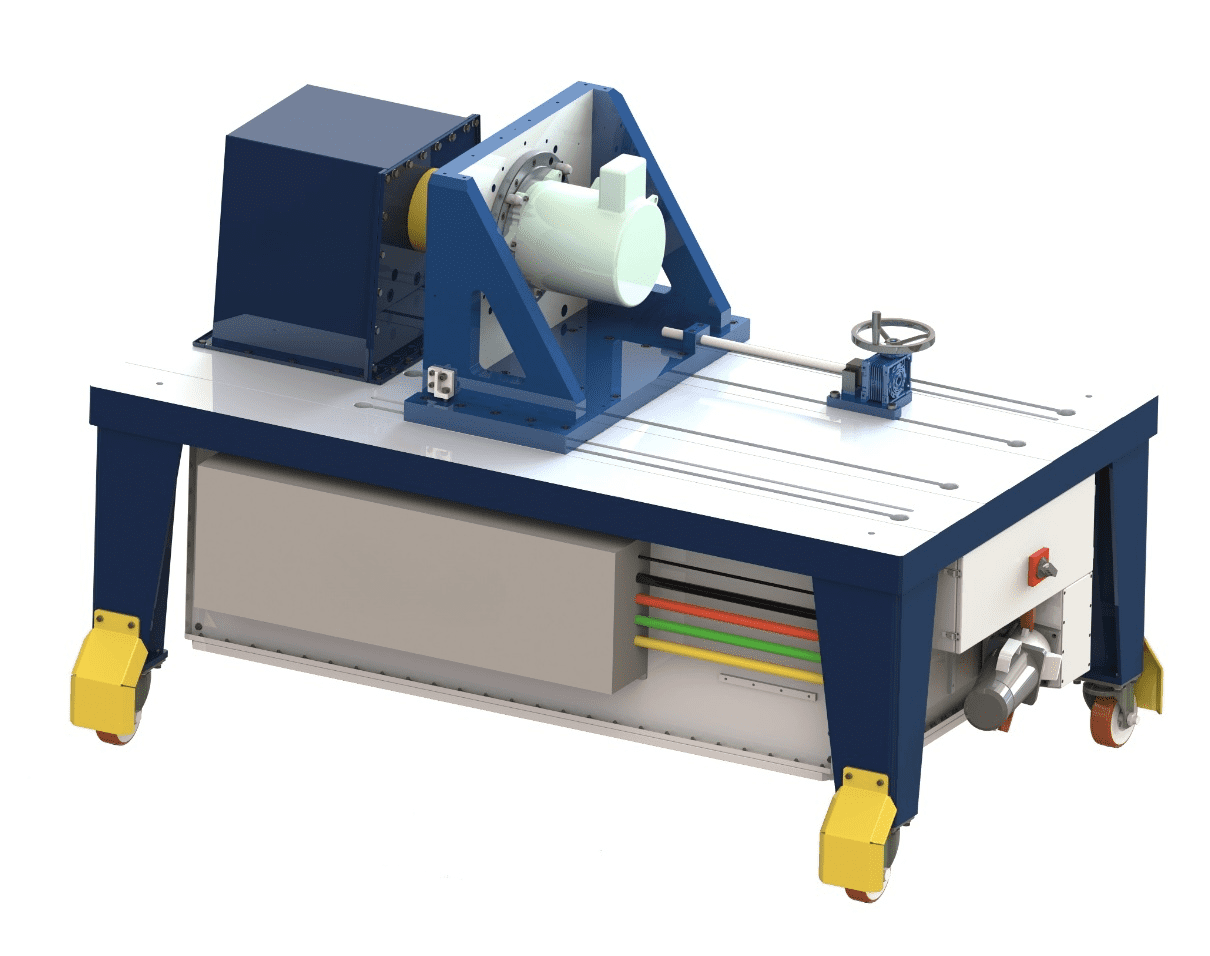
Free Edyno ist ein EMC -Testlastsystem für Motor und Controller. Es wird ein elektrisches Dynamometer verwendet, das von vier Quadrantenfrequenzwandler gesteuert wird, um einen beliebigen Lastmodus des elektrischen Antriebssystems zu simulieren, wie Beschleunigung, Verzögerung, konstante Geschwindigkeit, konstantes Drehmoment und so weiter.
Der elektrische Dynamometer und der Frequenzwandler sind in die mobile Plattform integriert, die auf dem Hochleistungs -Industrie -Universal Rad.
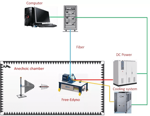
Das kostenlose Edyno -Steuerungssystem kann das Dynamometer durch optische Faser- und Remotedatenübertragung steuern. Benutzer müssen nur die Stromversorgung und das Kühlwasserrohr anschließen, um das System remote zu steuern.
1) Drehmomentmessgenauigkeit: ± 0.05% Fs
2) Messauflösung des Geschwindigkeitssensors: 1024ppr
3) Drehmomentkontrollgenauigkeit: ± 2% Fs
4) Geschwindigkeitsregelgenauigkeit: ± 2 U / min
5) Temperaturmessbereich: – 50 ℃ ~ 200 ℃
Free-edyno nimmt isoliertes industrielles Universalrad ein, Dies kann den schwimmenden Zustand von Fahrzeugreifen simulieren. Die Welle des getesteten Motors und die Ausgangswelle des Dynamometers kann durch Isolierkupplung oder Metallkopplung angeschlossen werden, Dies kann verschiedene Verbindungszustände des getesteten Motors simulieren.
Das Free-Edyno-System nimmt eine einzigartige Abschirmbehandlungstechnologie an, integriert das elektrische Dynamometer, Frequenzwandler, usw. in eine geschlossene Metallabdeckung, und nimmt einen speziellen elektrostatischen Leitmechanismus an, um sicherzustellen, dass das System die Anforderungen des EMC -Tests erfüllen kann. Die EMC -Leistung erfüllt die Standardanforderungen von ISO vollständig 11452-2, und CISPR25.
Die Installationsplattform des getesteten Motors kann auch als feste Plattform mit T-Slot ausgelegt werden. Wir können L-förmige L-förmige Unterstützung für die Installation des getesteten Motors anbieten. Die Oberfläche der Installationsplattform wurde mit einer Kupferplattenmontageoberfläche ausgelegt, Dies kann sehr guten elektrischen Kontakt mit der Kupferplatte auf dem Testtisch herstellen.
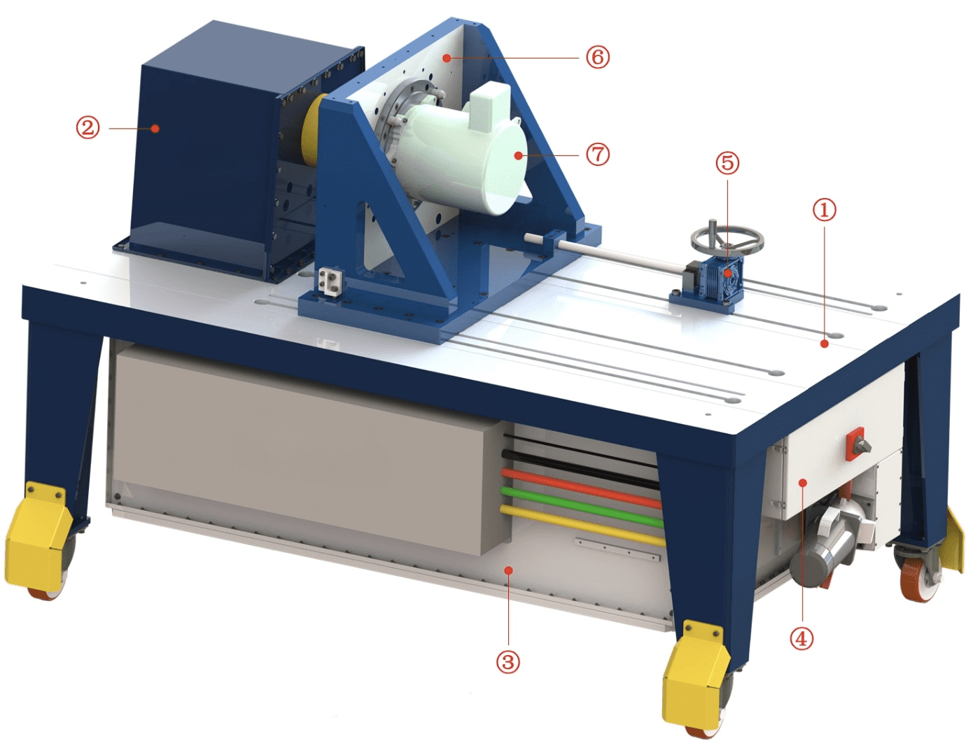
①–Installationsplattform ②–Antriebssystem ③–Dynamometer -System ④–Power in Box ⑤–Mobiler Mechanismus ⑥–L-förmige Unterstützung ⑦–getesteter Motor
Wir können die L-förmige Unterstützung bewegen, indem wir das Handrad am Reduzierer des mobilen Mechanismus drehen.
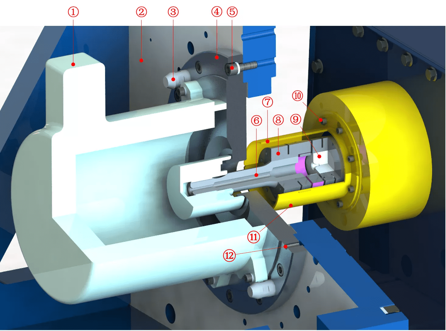
Die Präzisions-L-förmige Unterstützung ist auf der Installationsplattform konzipiert, Dies sorgt für die genaue Koaxialität des getesteten Motors mit der Dynamometerausgangsschacht. Stellen Sie einfach sicher, dass der getestete Motor mit dem Montageflansch koaxial ist.
①–getesteter Motor ②–L-förmige Unterstützung ③–Leitfaden Pin ④–Montageflansch für Motor ⑤–Schraube zum Montieren von Flansch ⑥–Welle anschließen ⑦–Schutzabdeckung ⑧–elastische Kopplung ⑨–Leistungswelle ⑩–Schraube zur Schutzabdeckung ⑪–Schutzabdeckung
Das Mess- und Steuerungssystem besteht aus dem oberen Computerüberwachungssystem, Datenerfassungssystem, Sensormesssystem, Frequenzwandlersteuerungssystem, Hilfskontrollsystem für Testbett-Hilfsgeräte, Sicherheitsüberwachungssystem, Verwerfungswarnsystem, usw. Das Mess- und Steuerungssystem übernimmt Echtzeit Ethernet EtherCat als Hauptkommunikationsnetzwerk.
Die Sensoren in der anechoischen Kammer werden mit geringem Geräusch behandelt, was den EMC -Leistungsindex der anechoischen Kammer nicht beeinflusst. Die Notstop -Taste ist auf der Konsole im Kontrollraum und im Dynamometer gestaltet, Wenn eine Notstrench -Taste gedrückt wird, Das System kann sofort gestoppt werden, einschließlich Dynamometer, Frequenzwandler, Batteriesimulator, usw.
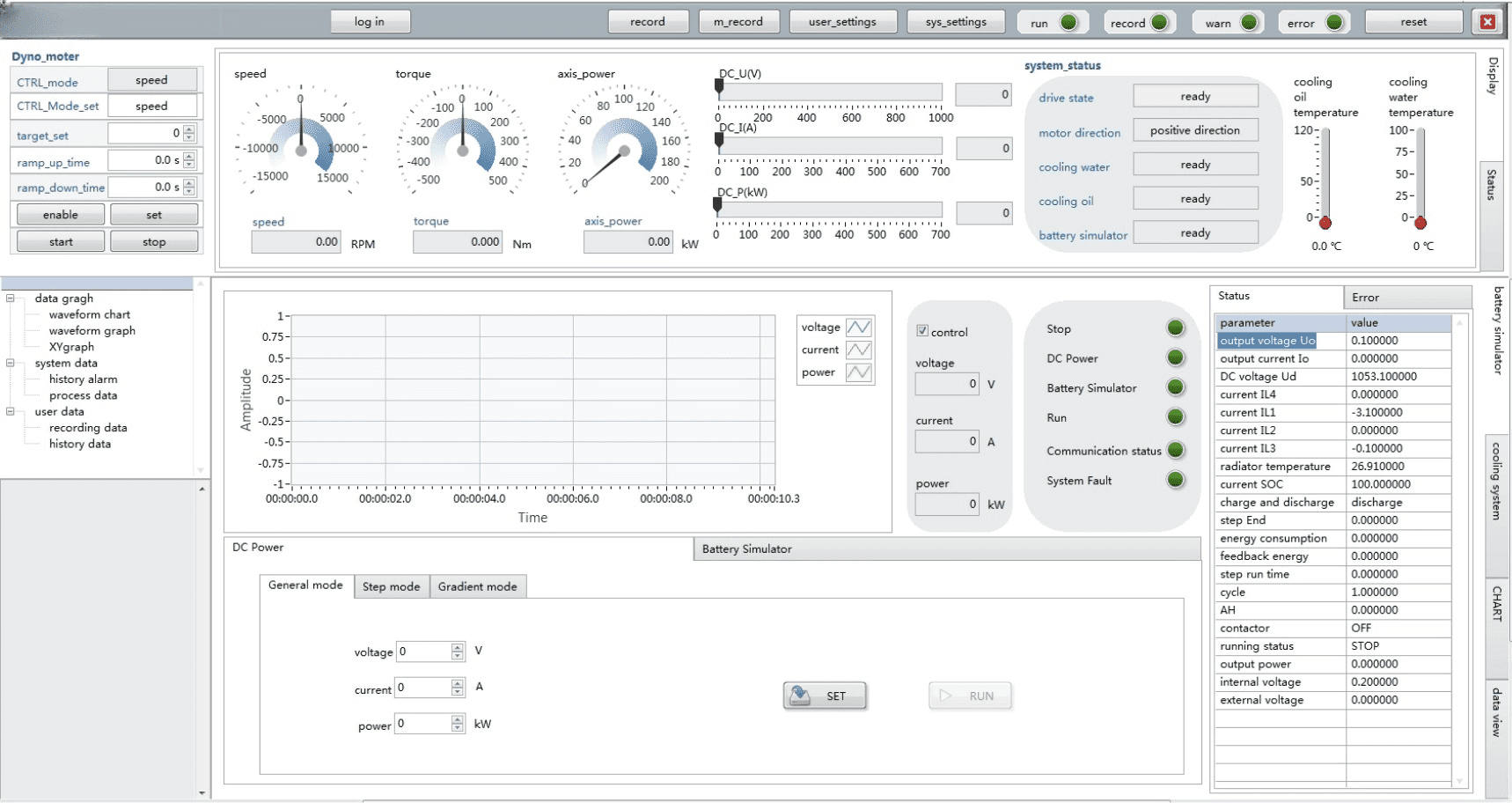
Das Dynamometer -Steuerungssoftware -System integriert die Dynamometer -Steuerung, Batteriesimulatorsteuerung, Kühlsystemsteuerung und Sicherheitsüberwachung. Jedes Subsystem kann remote überwacht werden.
Die Steuerschnittstelle des Testbetts wird hauptsächlich zur Steuerung des Dynamometers verwendet, Batteriesimulator, Kühlsystem, usw. Das Dynamometer kann Drehmoment- und Geschwindigkeitsregelmodi annehmen. Die Steuerungssoftware -Schnittstelle zeigt das Drehmoment an, Geschwindigkeitstemperatur, Strom und Spannung der bidirektionalen DC -Leistung und so weiter. Sie können das Dynometer steuern, die bidirektionale DC -Kraft, Kühlsystem durch das Steuerungssoftwaresystem. Die Steuerungssystemsoftware muss die folgenden Funktionen enthalten:
1) Konstante Geschwindigkeitsregelung des Dynamometers
2) Konstante Drehmomentsteuerung des Dynamometers
3) Benutzerdefinierte Operationstabelle
4) Messdatenanzeige und Speicherung
5) Begrenzung der Überwachung
6) Grafische Anzeige von Messungsergebnissen

