Automotive Electromagnetic Compatibility EMC Testing: Ensuring Safe and Reliable Vehicle Electronics
The solution plays a vital role in designing and ensuring the performance of automotive electronics. In Addition it refers to a device’s ability to function properly without causing, suffering from interference in its electromagnetic environment. In today’s cars, where electronics control everything from engine systems to entertainment features, ensuring EMC compliance is essential for smooth and reliable operation.
In the automotive industry, EMC testing is conducting to ensure that a vehicle’s electronic systems work seamlessly, without disrupting each other, or being affected by external sources of interference. The goal is to prevent electromagnetic interference (EMI) that could potentially compromise the performance and safety of the vehicle.
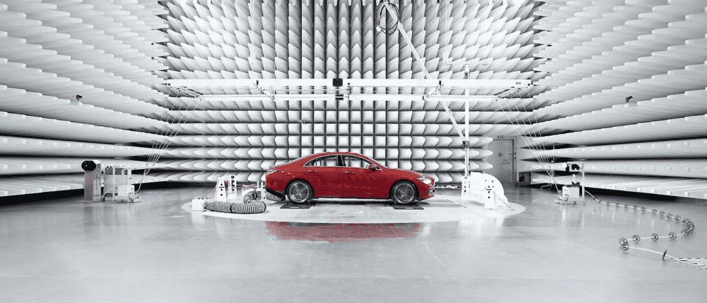
EMC testing helps automotive manufacturers meet regulatory standards, improving product quality, enhance vehicle safety. Ensuring the electronic components in a vehicle, which don’t emit unnecessary electromagnetic energy could interfere with nearby devices, Such smartphones or vehicles. the system also assesses the vehicle’s electronic resilience against external interferences, such as mobile phones or radio signals.
Furthermore vehicle EMC/EMI test system generally consists of an anechoic chamber or reverberation chamber, measuring instruments. In addition a hub dynamometer system that simulates the road load of the vehicle. As rotating hub dynamometer system, which simulates vehicle load. That designs as a two-wheel drive, four-wheel drive or more shaft drive dynamometer, according to the number of drive shafts of the vehicle. AS a result the dynamometer system can also adopt a structural type embedded in the turntable, or a mobile type.
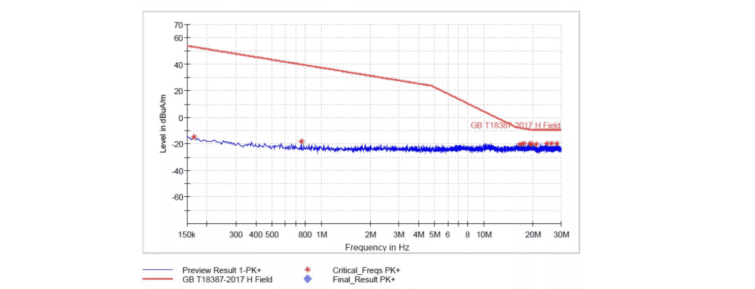
Emissions Testing: This part of the testing process measures the electromagnetic, which energy release by the vehicle’s electronic components. With purpose is to identify and reduce any emissions, therefore might interfere with other nearby electronic devices. Testing solution ensures that the vehicle, which complies with global regulatory standards for electromagnetic emissions.
Immunity Testing: Immunity testing evaluates how well the vehicle’s electronics perform, Moreover exposing to external electromagnetic fields. For example, it simulates interference from mobile phones, radio towers, or other electronic devices. System ensures that the vehicle’s systems remain operational and safe, even in environments filled with electromagnetic signals.
By conducting both emissions and immunity testing, automotive manufacturers ensure their vehicles are compatible with electromagnetic environments. It provides a smooth and safe driving experience for customers.
Since everything needs to be tested in the lab,Since tests perform on the real roads are expensive and not reproducible. Nevertheless realistic driving conditions must somehow should be simulated in the lab. As a result this is leading to a huge demand for new test systems and test cases. To keep pace with the growing speed of development – both for automotive manufacturers as well as their suppliers, test houses and inspection organizations.
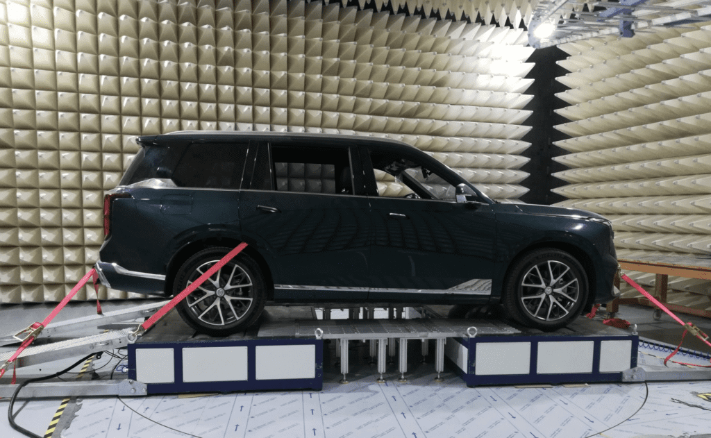
Fixed Stationary EMC Testing System designs to simulate realistic driving conditions for vehicle testing, specifically focusing on electromagnetic compatibility (EMC) assessments. Moreover it consists of two main units: a drum unit and a dynamometer unit. These work together to replicate the road load before and after the vehicle, with the added flexibility of adjustable distances between the drum units.
Dynamometer Unit: The dynamometer is typically embed within a turntable, Which rotates along with it or positions within the raised floor. In addition the dynamometer unit simulates the vehicle’s driving dynamics, road load by adjusting to the vehicle’s wheelbase. Test Bench demonstrates accurate torque or speed control during testing.
Setup Process: Before testing begins, Moreover dynamometer’s moving axle unit adjusts to match the vehicle’s wheelbase. The vehicle is then securely fix into the hub using a ratchet strap. Both the front and rear of the vehicle locked in place. Therefore the exhaust pipe is connected, testing is initiating as well.
Modular Assembly: Each dynamometer unit operates independently, allowing for flexible and modular configurations.
Torque or Speed Control: The dynamometer can control either torque or speed independently to accurately simulate road loads.
Anechoic or Reverberation Chambers: The test bench is compatible for use in anechoic or reverberation chambers, essential for precise EMC testing.
Customizable Design: The bench can tailor to meet specific user needs, offering a high level of flexibility.
Adjustable Spacing: The multi-axis dynamometer spacing can adjust to accommodate vehicles with varying wheelbases.
Optional Upgrades: The bench can equip with additional features such as an automatic driving robot. Exhaust emission system, and vehicle windward system to enhance testing capabilities.
Class 5 Shielding: Cutting-edge shielding technology ensures compliance with CISPR 25 Class 5 standards for electromagnetic compatibility.
High Accuracy: The dynamometer offers precise torque and speed control, ensuring high repeatability and reliability in testing.
Turntable Integration: It can embed in a turntable or beneath the raised floor, offering flexibility in installation.
Vehicle Fixing: The vehicle fixing device is integrating with the dynamometer body, ensuring secure and reliable vehicle positioning during tests.
Tire Burst Detection: The bench includes a vehicle tire burst detection device to prevent accidents during testing.
Centering Detection: A vehicle centering detection device ensures accurate alignment of the vehicle during setup.
The recommended dynamometer parameters should align with the specific vehicle type and testing requirements. Such as torque capacity, speed range, and load simulation capabilities. these parameters help to ensure the dynamometer accurately simulates real-world driving conditions. Evaluate the vehicle’s electromagnetic compatibility under various scenarios.
Moreover the test bench offers comprehensive testing capabilities for automotive manufacturers. Ensuring their vehicles meet the stringent EMC standards, which requires for modern electronic systems. Solution give high performance, versatility, therefore adaptability for a range of automotive testing environments.
EC-A22-X(a)
EC-B34-X
EC-B74-X
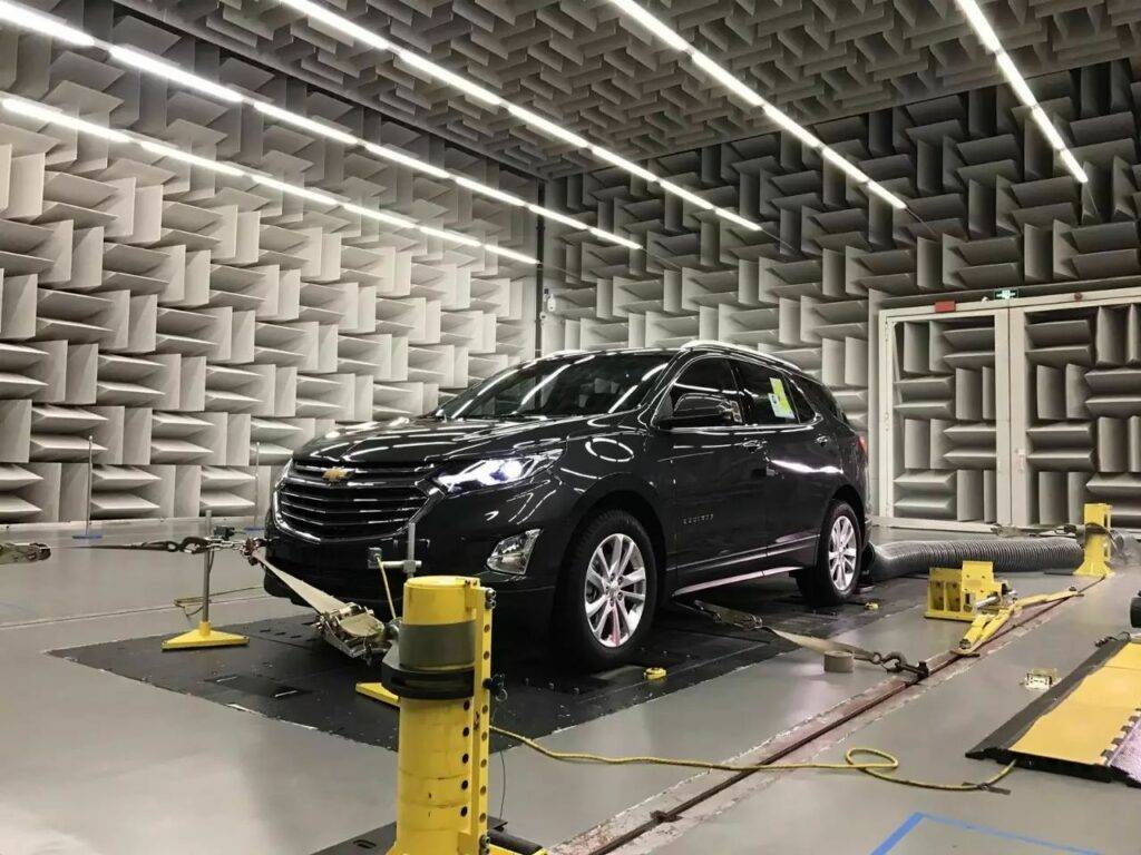
The Portable Mobile Vehicle EMC Testing System is a Cutting-edge, highly flexible solution. Which designs to efficiently evaluate the electromagnetic compatibility (EMC) of vehicles. Its modular design allows for easy assembly, transportation, in addition adaptation to various vehicle types and sizes. making it an ideal choice for manufacturers seeking mobility and flexibility in their testing processes.
System is Equipping with heavy-duty load-bearing universal wheels, in addition the test bench can easily maneuver into an anechoic chamber. As crucial as anechoic chambers design to minimize external electromagnetic noise and reflections. Ensuring the test results are accurate and uncontaminated by outside interference.
Once inside the chamber, the bench employs an adjustable bracket, Which places in the designating support position to stabilize the vehicle. In addition the vehicle is connecting to various systems including:
Power cable for energizing the vehicle’s electronics.
Communication fiber for real-time data transfer.
Pneumatic pipeline to handle air pressure needs for systems like active suspension or braking.
This setup ensures that the vehicle’s systems function as they would in real-world conditions, providing a comprehensive test environment.
To prevent any movement during the testing phase, the vehicle is secured using a ratcheting harness. Moreover this mechanism guarantees stability, which is critical for achieving precise and reliable test results.
With the vehicle secured and operational, the EMC testing process begins. The equipment evaluates two key aspects of electromagnetic compatibility:
Emissions Testing: Measures the electromagnetic energy emitted by the vehicle’s electronic components. Such as the engine control unit (ECU) and infotainment systems. This helps identify any potential interference that could affect the vehicle’s performance or interfere with nearby devices.
Immunity Testing: Assesses how well the vehicle’s systems resist external electromagnetic fields. Simulating environments filled with electronic devices (like urban areas). In addition vehicle is exposed to various frequencies and field strengths. Allowing engineers to evaluate its resilience and ensure it meets the necessary industry standards.
Modular Assembly: Each dynamometer unit is a modular, independent unit, offering flexible setup and easy integration into various testing environments.
Independent Control: Each dynamometer can independently simulate road load, by controlling torque or speed. Providing a comprehensive and accurate load simulation.
Anechoic and Reverberation Chamber Compatibility: The bench is versatile enough to uses in anechoic chambers for precise electromagnetic testing. Reverberation chambers to simulate real-world electromagnetic conditions.
Customizable Design: The test bench can be customized to meet specific user requirements. Offering the flexibility needs for different vehicle types and testing needs.
Adjustable Spacing: The multi-axis dynamometer spacing is adjustable, making the system adaptable to vehicles with various wheelbases.
Optional Features: The equipment can equip with additional components such as:
Automatic driving robot for autonomous vehicle testing.
Exhaust emission system for testing vehicle emissions.
Vehicle windward system for simulating airflow conditions.
Cutting-edge Shielding Technology: The testing system meets the Class 5 requirements of CISPR25, ensuring compliance with industry standards for electromagnetic shielding.
High Accuracy and Repeatability: The dynamometer offers precise torque and speed control, ensuring high repeatability and reliability in testing.
Turntable or Raised Floor Integration: The dynamometer can integrating into a turntable or installed beneath a raised floor, offering flexibility in setup.
Secure Vehicle Fixing: The vehicle fixing device is integrated with the dynamometer body, ensuring secure and reliable vehicle positioning throughout the testing process.
Tire Burst Detection: The bench includes a vehicle tire burst detection device to enhance safety during testing.
Vehicle Centering Detection: A vehicle centering detection device ensures precise vehicle alignment for accurate testing results.
The Portable Mobile Vehicle EMC Testing System provides a flexible, reliable, and accurate solution for automotive manufacturers. Looking to ensure their vehicles meet strict electromagnetic compatibility standards. With its modular design, for example customizable features, and high-precision testing capabilities. Which offers comprehensive testing for emissions and immunity, ensuring vehicles perform optimally in real-world electromagnetic environments.

We provide the torquemeters, couplings, flywheels, spindles & test rigs for both helicopter and aero engine component testing
We provide test solution for marine engines, propulsion systems, electric motors, generator sets, transmission gearboxes, auxiliary power systems, exhaust gas systems, and spare parts for ships
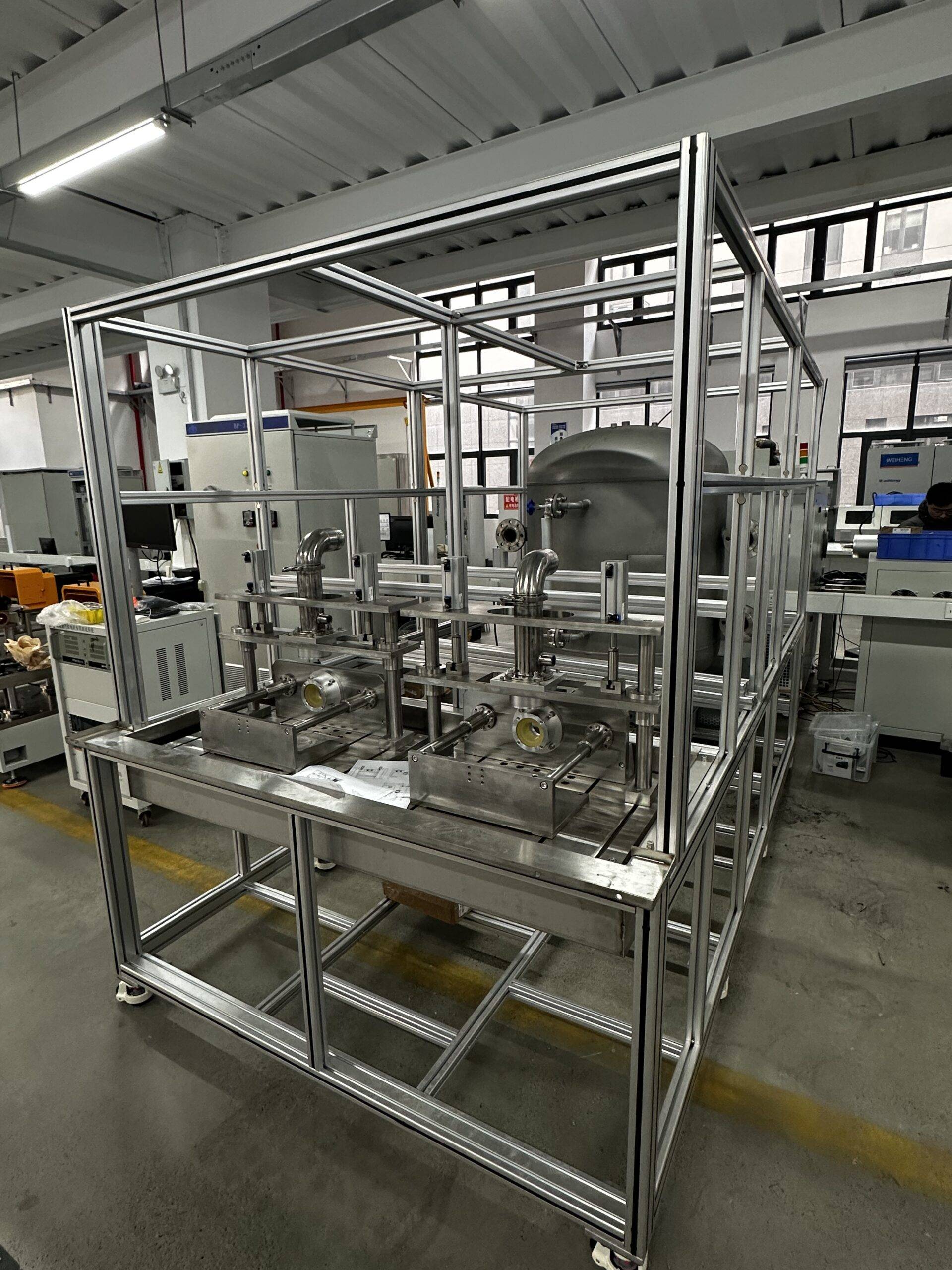
Water pump testing system is a specialized equipment used for performance testing of water pumps, commonly used to assess key parameters such as flow, head, power, and efficiency.
For any questions or support, please reach out via email at [email protected].
We aim to respond promptly.
Need immediate assistance? Call us at +86 156 1877 0706.
Our team is ready to assist you.
We welcome you to visit our office located at 3F, Building 2, NO.511 Xiaowan Road, Fengxian, Shanghai, China.
Let's discuss your needs in person.

© 2025 Shanghai EconoTechnology Co., Ltd. All rights reserved.
Empowering innovation through reliable testing solutions.