Defini comme langue par défaut
E-Axle Test Bench

E-Axle Test Bench

Electric drives are at the heart of both battery electric vehicles (BEVs) and fuel cell electric vehicles (FCEVs), As manufacturers face growing demands for industrialization and increased production volumes, Our comprehensive solutions support every phase of the project lifecycle—from concept development to implementation and operation. These solutions are designed to cater to a wide range of vehicles, including passenger cars, as well as light and heavy commercial vehicles.

The drive system of an electric vehicle (EV) comprises several key components. Central to this is the e-axle or electric drive unit (EDU), which integrates the electric motor, transmission, and inverter. While we provide dedicated testing solutions for each individual component, it is equally important to test the fully assembled e-axle to identify and address potential assembly-related defects, such as Noise, Vibration, Harshness (NVH) and EMC/EMI testing, which significantly impacts driver and passenger satisfaction and ensure the safety of the vehicle

The system can be 3ways/1 input+2 output, 4 ways, 5 ways, which can be integrated as powertrain testing solution
E-Axle Test Bench​

The comprehensive 3-in-1 electric axle test benches for both light-duty and heavy-duty vehicles address crucial factors such as performance, durability, noise, vibration, and harshness (NVH), as well as electromagnetic compatibility (EMC). These advanced test benches are designed to support manufacturers in developing sustainable electric drive systems that meet the highest standards of performance and quality in the automotive industry. By thoroughly assessing these key areas, manufacturers can ensure their electric axles are reliable, efficient, and capable of delivering optimal performance under real-world conditions.

E-Axle

Light-duty electric axle

We offer a customized solution for the development and validation of light-duty e-axles, whether for single or dual motor configurations. With shortest lead times, manufacturers can quickly begin lifecycle and thermal endurance testing, as well as detailed electrical, mechanical, and thermal property analysis. This advanced test system enables precise performance and functional testing at speeds up to 20,000 rpm and power levels up to 400 kW, supported by a direct drive dynamometer, flexible multi-channel cooling conditioning, and a climatic chamber for comprehensive environmental simulation.

The light-duty electric axle test bench is a customizable solution tailored to the specific needs of manufacturers, whether they are working with single or dual motor configurations. This flexibility enables engineers to develop and validate various units under test (UUTs) efficiently. Equipped with advanced instrumentation and testing capabilities, the test bench allows for comprehensive assessments of the electric axle’s performance characteristics. Its design ensures quick adaptation to different configurations and testing scenarios, making it easier for manufacturers to optimize their electric drive systems for a wide range of applications.

A key advantage of the light-duty electric axle test bench is its rapid delivery time, which allows clients to perform essential in-service lifetime and thermal endurance testing with minimal delay. This expedited timeline is especially critical for manufacturers aiming to bring their products to market quickly while ensuring compliance with rigorous industry standards. The test bench provides valuable insights into mechanical, electrical, and thermal properties, helping engineers identify potential issues early in the development process. By conducting these thorough evaluations, manufacturers can refine their designs, enhance durability, and improve overall performance, ultimately leading to the successful deployment of high-quality electric drive systems in light-duty vehicles.

Heavy-duty electric axle

The Heavy Duty test system is a standardized solution designed for the development and validation of e-axles in commercial vehicles, specifically tailored for trucks and buses. It enables comprehensive lifecycle testing under realistic, vehicle-like conditions. The system supports precise performance and functional testing, with capabilities of up to 20,000 rpm and 400 kW. Equipped with a direct-drive dynamometer, flexible multi-channel cooling conditioning, and a climatic chamber for environmental simulations, it ensures that the e-axles perform optimally across various operating conditions.

The X way-in-1 electric axle test bench is engineered to meet the temperature and service lifespan certification requirements for electric drive units. This system is optimized for efficient testing, allowing seamless integration of duty cycles avec pre-configured standardized cycles for temperature aging and lifespan certification during the operation of the Unit Under Test (UUT). This flexibility ensures that manufacturers can thoroughly evaluate the performance and durabilityof their electric drive systems, resulting in more robust and reliable products.

Electric axle test bench for NVH/EMC

The electric axle test bench for NVH is designed to redefine silence, comfort, and overall performance in both light-duty and heavy-duty e-axle solutions. With exceptionally low operating noise levels, it ensures superior NVH performance, making it ideal for the development of quiet and smooth electric powertrains. The system also features semi-automatic track width and wheelbase adjustments, which streamline high-end NVH development, providing engineers with the flexibility to optimize performance easily.

This innovative solution sets new industry standards for NVH engineering in both current and future e-powertrains, ensuring that electric axles deliver not only optimal performance but also maximum user comfort and satisfaction. It is designed to meet the demands of a wide range of mobility applications, enhancing the driving experience and making it more enjoyable for all users.

To measure the electromagnetic compatibility (EMC) of e-drive systems and assess both their emissions and immunity to interference, specialized EMC test systems are essential. We offer precise EMC measurements and testing in accordance with the CISPR 25 standard, ensuring that your systems meet the most stringent industry regulations.

This solution allows for effective evaluation of both the emissions and immunity of your e-axle components, guaranteeing the reliability and compliance of electric drive systems. By using this testing approach, manufacturers can ensure their systems are ready for future mobility applications, offering both performance and regulatory compliance.

Applications of Electric Drive Unit and Electric Axle Test Bench:

  1. Service Lifespan Testing

    • Assessing the durability and longevity of electric drive systems and axles under simulated real-world conditions.

  2. High-Speed and Torque Testing

    • Evaluating performance at both high speeds and high torque levels to ensure optimal functionality under demanding operating conditions.

  3. Torque Differential and Speed Difference Testing

    • Measuring and analyzing variations in torque and speed across the electric axle or drive unit to ensure smooth operation and performance balance.

  4. Peak Power Testing

    • Assessing the system’s ability to handle short bursts of peak power, ensuring the e-drive can deliver maximum output when required.

  5. Electrical to Mechanical Power Efficiency Testing

    • Analyzing the conversion efficiency from electrical to mechanical power, helping to identify areas for improvement in energy use.

  6. Torque Interface to Electric Drive in No-Throttle Test

    • Evaluating torque response and control when the throttle is not engaged, simulating idle or coasting conditions.

  7. xCU Interface to E-Drive for Throttle Test

    • Testing the responsiveness and control of the e-drive when interfaced with the throttle control unit (xCU), simulating real-world acceleration and deceleration.

  8. Driving Cycle Testing

    • Simulating real-world driving conditions by using predefined driving cycles to assess the overall performance and efficiency of the electric drive unit.

  9. Vibration Analysis

    • Analyzing vibrations generated during operation to identify and mitigate issues related to mechanical resonance, efficiency losses, or NVH (Noise, Vibration, and Harshness) concerns.

Thermal Examinations:

  1. Cooling System Stability Test

    • Testing the stability and effectiveness of the cooling system to ensure that the electric drive unit maintains optimal operating temperature.

  2. High-Temperature Operating Endurance (HTOE)

    • Assessing the electric drive’s ability to operate reliably under high-temperature conditions over extended periods.

  3. Powered Thermal Cycle Endurance (PTCE)

    • Evaluating the system’s ability to withstand repeated thermal cycles, simulating various temperature extremes that may occur during operation.

These testing capabilities ensure that electric drive units and axles are thoroughly validated for performance, reliability, and efficacité, preparing them for integration into next-generation mobility solutions.

High-speed motor test bench

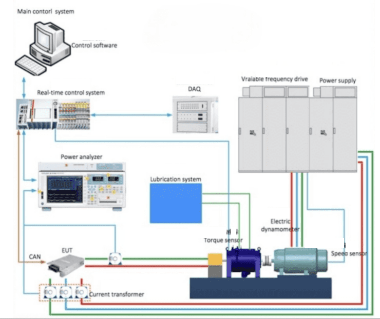
The high-speed motor test bench is a specialized system designed to evaluate and validate the performance of high-speed electric motors under various operating conditions. It consists of several key components, including a dynamometer, real-time controller, data acquisition system, and various sensors.

Electric drivetrain development is faster, but still complex due to diverse motor types and designs. Econotest offers specialized dynamometers, software, and tools for testing electric vehicle drivelines. High-speed motor test benches evaluate performance, NVH, EMC, and durability of electric propulsion systems. These testing capabilities help manufacturers meet strict quality and performance standards for electrified drivetrains. Econotest’s solutions address challenges in testing EESM, ASM, and PMSM motors in various driveline configurations. Comprehensive testing ensures electric vehicle drivetrains are certified quickly and to high-quality standards. Advanced tools and procedures from Econotest supports rapid development of modern electric propulsion systems.

We’re able to do the ODM/OEM with customization of Brand, Color,Packaging, Size and Parameters.

high-speed motor test bench

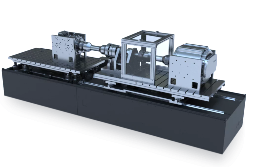
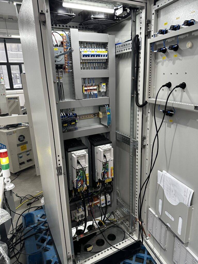
The high-speed motor test bench‘s real-time dynamic control system uses a real-time controller to achieve speed and torque control, simulating actual load conditions. The main control system can communicate with and control environmental chambers, power analyzers, cooling systems, and EUTs. The data acquisition system collects signals from torque sensors, vibration sensors, temperature sensors, pressure sensors, and other sensors, transmitting them at high speed to the main control system. Sensor data can be displayed, saved, and processed in the software interface

1. High-speed with high-power motor test bench:

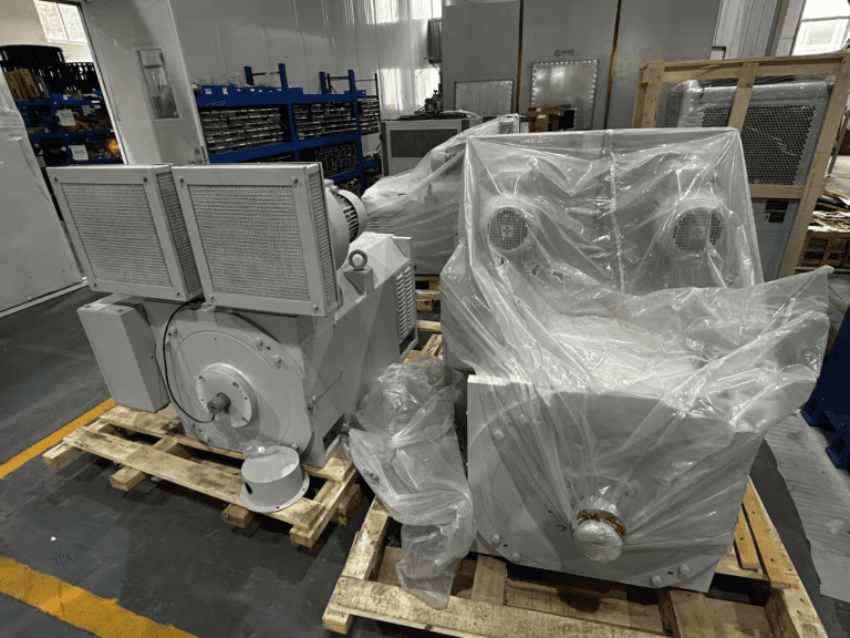
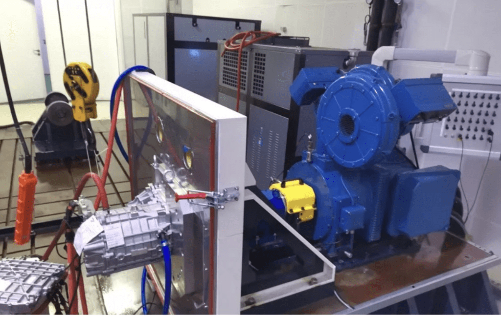
High-Speed High-Power Motor Test System This system is suitable for various high-speed motor applications, including new energy vehicle drive motors, high-speed air compressor motors, and high-speed magnetic levitation motors. The installation platform can be designed according to the motor under test, with options for end flange or base mounting structures

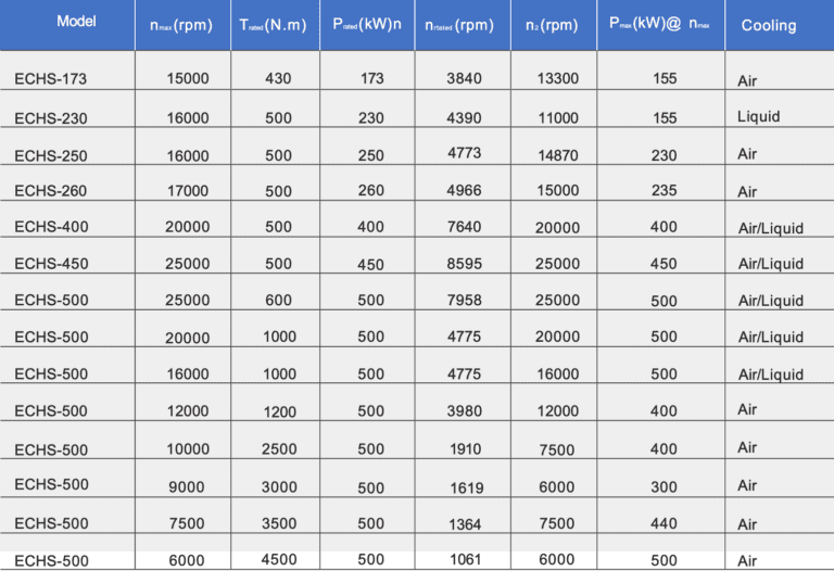
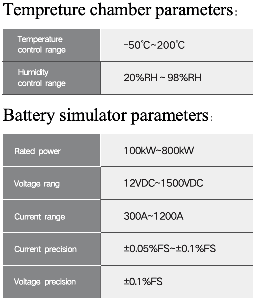
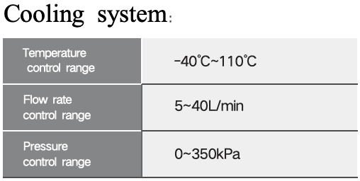
Motor Test Bench Selection Specifications The dynamometer is selected based on the characteristic curve of the motor under test. It typically uses four-quadrant inverter control and can operate in both motor and generator states. The system can be optionally equipped with high and low-temperature environmental chambers, battery simulators or bidirectional DC power supplies, power analyzers, and cooling systems.

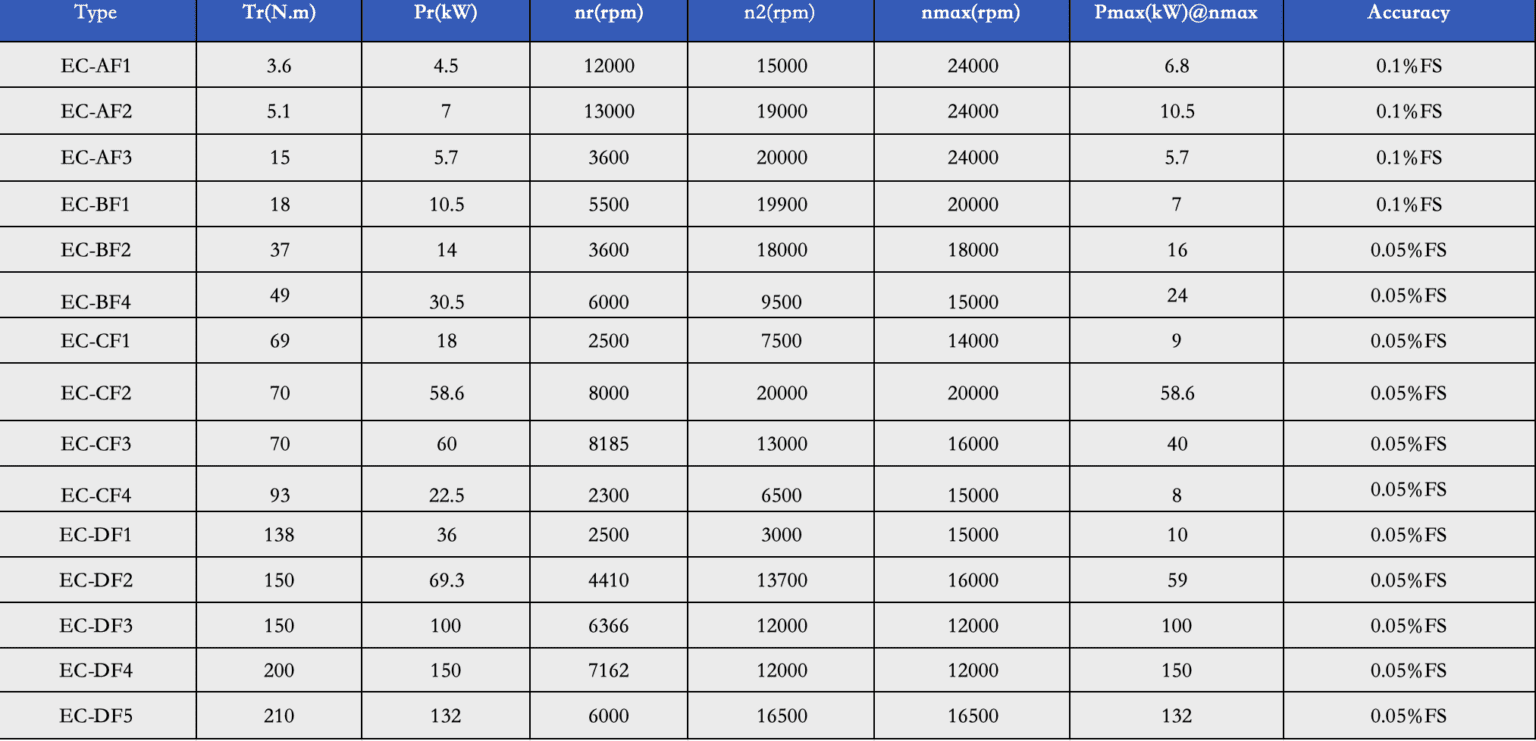
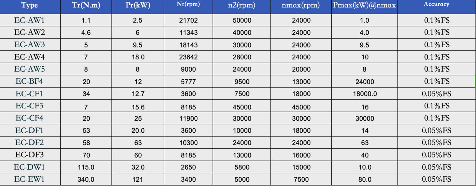
Main parameters are as follows, all Parameters can be customized by requirement :

High-speed with high-power motor test bench
Tempreture chamber parameters:
Cooling system:

2.High-speed with low-power motor test bench:

This system is used for testing small power high-speed motors, such as small power aviation generators, robot motors, small high-speed compressor motors, and machine tool spindle motors. The installation platform can be designed according to the motor under test, with options for end flange or base mounting structures

Test bench selection specifications

The test bench is selected based on the characteristic curve of the motor under test. It typically uses four-quadrant inverter control and can operate in both motor and generator states. The system can be optionally equipped with high and low-temperature environmental chambers, battery simulators or bidirectional DC power supplies, small power adjustable DC power supplies, power analyzers, and cooling systems. Depending on noise requirements, water-cooled or air-cooled dynamometers can be selected

1.Specification with air-cooling:

high-speed motor bench

2.Specification with Liquid-cooling:

high-speed motor bench
HIGH SPEED MOTOR

3. High speed motor test bench

High-Speed Motor Test Bench Overview

  1. Purpose and Application: The high-speed motor test bench is designed to test motors that operate at speeds exceeding 60,000 rpm. It is commonly used in applications like high-speed compressor motors. Our test system can handle motors with speeds up to 165,000 rpm.

  2. System Components: The high-speed motor test system is composed of several key components, including:

    • Dynamomètre
    • Dynamometer driver
    • Braking resistor
    • Speed-increasing gearbox
    • DC power supply
    • Power analyzer or power meter
    • Control system
    • Mechanical system
    • Sensor measurement system And other associated parts.
HIGH SPEED Motor
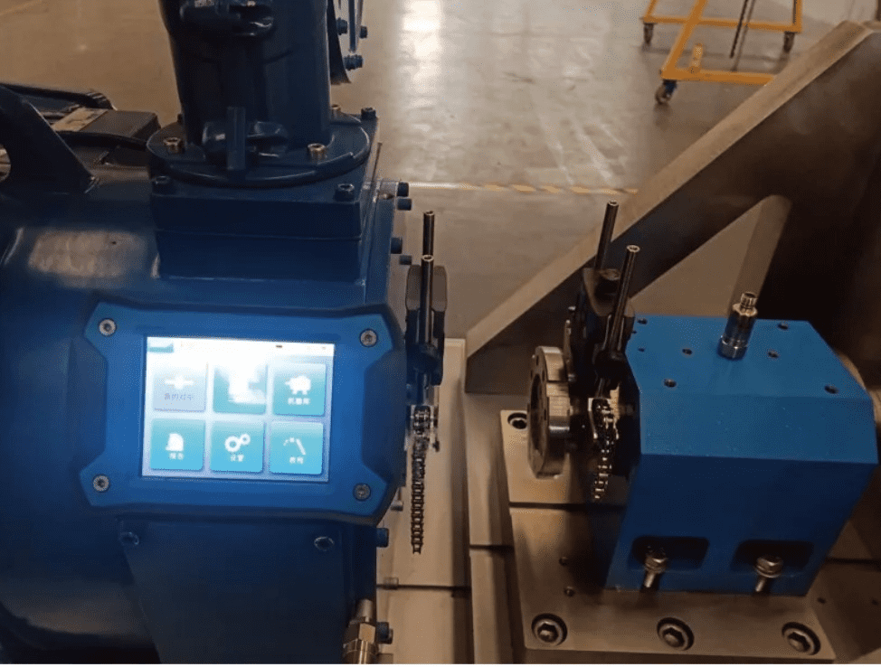
  1. High-Speed Gearbox: The ultra-high-speed gearbox is a two-stage power distribution gearbox with coaxial input and output shafts. Key specifications include:

    • Rated output speed: 165,000 rpm
    • Rated output torque: 1.5 Nm
    • Rated power: 25 kW
    • Service life of all gearbox components: >10,000 hours

    Additionally, the gearbox includes a lubrication pumping station provided by the supplier, which is adjusted prior to shipment to ensure optimal performance.

  2. Test Piece Torque Measurement: Torque is measured directly from the test piece to avoid transmission losses that could affect the data. Unlike traditional methods where a torque sensor is placed on the low-speed end of the system, this direct measurement provides more accurate readings for high-speed motors.

  3. Test Piece Connection: To accommodate different test specimens and ensure ease of tool replacement, the system includes a torque flange, a transitional spline flange, and a spline between the bearing housing and the motor’s input shaft. This design helps to reduce torsional vibrations and ensures reliable connections during testing.

Hight Speed Motor Test Bench Architecture

  1. Real-Time Dynamic Control System: The motor test bench features a sophisticated real-time control system that allows for precise speed and torque control through a real-time controller. It simulates actual loading conditions and can communicate with various components like the environmental chamber, power analyzer, cooling system, and the Equipment Under Test (EUT). The system collects data from a wide range of sensors, including torque, vibration, temperature, and pressure sensors, and transmits it rapidly to the main control system. The collected data is then displayed, saved, and processed through the software interface.

  2. Key Technical Indicators:

    • Torque Measurement Accuracy: ±0.05% FS to ±0.1% FS
    • Pulse Resolution of Speed Sensor: 1024/600 ppr
    • Torque Control Accuracy: ±0.5% to ±1%
    • Speed Control Accuracy: ±0.01% FS
    • Maximum Vibration Speed of Dynamometer: ≤ 2mm/s (independent), ≤ 3.5mm/s (under load)
    • Temperature Rise of Intermediate Bearing: ≤ 35°C
    • Vibration Speed of Intermediate Bearing Seat: ≤ 2mm/s (independent), ≤ 3.5mm/s (under load)
    • Test Motor Current Channels: 4 or 6 channels
    • Test Motor Voltage Channels: 4 or 6 channels
    • Power Analyzer Measurement Accuracy: ± (0.05%/0.1% of reading + 0.05%/0.1% of range)
    • Data Acquisition System Sampling Rate: 1 kHz
    • User Data Acquisition Channels: Optional
    • Temperature Measurement Range: -50°C to 200°C
    • Vibration Sensor Range: 0-20mm/s
  3. Main Test Items:

    • Power and torque characteristics of motors with controllers
    • Temperature rise testing of motors with controllers
    • Locked-rotor tests for motors with controllers
    • Verification tests for motor controller control strategies
    • Maximum speed tests for motors and controllers
    • Regenerative energy feedback tests (braking tests)
    • External characteristics of motors
    • Development and optimization tests of motor-controller powertrains
    • Performance tests and calibration of motor-controller systems
    • Efficiency map testing
    • Accelerated response testing
    • Torque response testing
    • Durability tests with steady-state cyclic loading
    • Back EMF constant and waveform analysis
    • Electromechanical time constant testing
    • Response characteristics testing for high-speed small motors
  4. Key Technologies of the Motor Test Bench:

    4.1 High-Performance Electric Dynamometer: The dynamometer, a core component, features a low moment of inertia, minimal vibration, compact size, and high acceleration performance. It also offers efficiency benefits, along with real-time monitoring of bearing conditions, temperature, and windings.

    4.2 High-Dynamic Real-Time Control System: The test bench uses an embedded real-time controller for high-dynamic control, supporting EtherCAT/Profinet communication. It boasts a no-load dynamic response time of under 10ms, allowing it to meet complex variable conditions during testing.

    4.3 Electrical Parameter Measurement System: The system uses high-precision power analyzers and current transformers for accurate measurements of efficiency, actuel, voltage, and other motor and controller parameters. It simultaneously measures torque and speed.


HIGH SPEED MOTOR
HIGH SPEED MOTOR

4.4 Precision Mechanical Structure: Components are machined with high precision, ensuring that shaft coaxiality is better than 0.02mm, providing optimal alignment and performance during testing.

4.5 Precision High-Speed Bearing Support: High-speed angular contact ceramic ball bearings are used, with spring preload to maintain bearing stability. The temperature rise does not exceed 35°C, and vibration speed stays under 2.5mm/s (RSM) at maximum speeds. The bearings are maintenance-free and capable of operating continuously for up to 20,000 hours.

4.6 Safety Protection Measures: The system is equipped with multiple layers of safety protections:

  • Real-time monitoring of bearings, temperature, vitesse, couple, and vibration
  • Real-time monitoring of motor vibration and safety cover protection
  • Electronic control system includes protection for short circuits, overcurrent, overvoltage, leakage, and power failures
  • Software includes an alarm system for when monitored values exceed preset thresholds, with three levels of protection
  • Durability tests include trend predictions based on historical data, with alerts if abnormalities are detected.

4.7 Easy Installation: The L-shaped mounting bracket is designed with a positioning stop and mounting surface, allowing for easy and quick installation of the test motor. It also features an interface for high and low temperature chambers, ensuring that the test motor remains coaxial with the shaft system, even when temperature changes occur. Vibration sensors monitor motor vibrations in real time.

4.8 Complete Monitoring Software: The motor test bench software has a modular architecture, enabling users to customize test parameters and processes. It supports speed and torque control, temperature and speed monitoring, and includes safety features like automatic calibration and limit monitoring. The software supports both open-loop and closed-loop control.

4.9 Shaft Alignment Measures: For high-speed shafting, the system ensures shaft coaxiality is no greater than 0.02mm using laser alignment tools and fine-tuned mechanical structures.

4.10 Shafting Dynamic Balance Treatment: The shaft system is balanced to a G1 accuracy level, and dynamic balance is performed onsite using specialized tools. Counterweight features are integrated into the flange design, and an on-site dynamic balancer ensures proper balance during operation.

HIGH SPEED MOTOR
erreur: Le contenu est protégé !!