Defini comme langue par défaut
E-Axle Test Bench

E-Axle Test Bench

Electric drives are at the heart of both battery electric vehicles (BEVs) and fuel cell electric vehicles (FCEVs), As manufacturers face growing demands for industrialization and increased production volumes, Our comprehensive solutions support every phase of the project lifecycle—from concept development to implementation and operation. These solutions are designed to cater to a wide range of vehicles, including passenger cars, as well as light and heavy commercial vehicles.

The drive system of an electric vehicle (EV) comprises several key components. Central to this is the e-axle or electric drive unit (EDU), which integrates the electric motor, transmission, and inverter. While we provide dedicated testing solutions for each individual component, it is equally important to test the fully assembled e-axle to identify and address potential assembly-related defects, such as Noise, Vibration, Harshness (NVH) and EMC/EMI testing, which significantly impacts driver and passenger satisfaction and ensure the safety of the vehicle

The system can be 3ways/1 input+2 output, 4 ways, 5 ways, which can be integrated as powertrain testing solution
E-Axle Test Bench​

The comprehensive 3-in-1 electric axle test benches for both light-duty and heavy-duty vehicles address crucial factors such as performance, durability, noise, vibration, and harshness (NVH), as well as electromagnetic compatibility (EMC). These advanced test benches are designed to support manufacturers in developing sustainable electric drive systems that meet the highest standards of performance and quality in the automotive industry. By thoroughly assessing these key areas, manufacturers can ensure their electric axles are reliable, efficient, and capable of delivering optimal performance under real-world conditions.

E-Axle

Light-duty electric axle

We offer a customized solution for the development and validation of light-duty e-axles, whether for single or dual motor configurations. With shortest lead times, manufacturers can quickly begin lifecycle and thermal endurance testing, as well as detailed electrical, mechanical, and thermal property analysis. This advanced test system enables precise performance and functional testing at speeds up to 20,000 rpm and power levels up to 400 kW, supported by a direct drive dynamometer, flexible multi-channel cooling conditioning, and a climatic chamber for comprehensive environmental simulation.

The light-duty electric axle test bench is a customizable solution tailored to the specific needs of manufacturers, whether they are working with single or dual motor configurations. This flexibility enables engineers to develop and validate various units under test (UUTs) efficiently. Equipped with advanced instrumentation and testing capabilities, the test bench allows for comprehensive assessments of the electric axle’s performance characteristics. Its design ensures quick adaptation to different configurations and testing scenarios, making it easier for manufacturers to optimize their electric drive systems for a wide range of applications.

A key advantage of the light-duty electric axle test bench is its rapid delivery time, which allows clients to perform essential in-service lifetime and thermal endurance testing with minimal delay. This expedited timeline is especially critical for manufacturers aiming to bring their products to market quickly while ensuring compliance with rigorous industry standards. The test bench provides valuable insights into mechanical, electrical, and thermal properties, helping engineers identify potential issues early in the development process. By conducting these thorough evaluations, manufacturers can refine their designs, enhance durability, and improve overall performance, ultimately leading to the successful deployment of high-quality electric drive systems in light-duty vehicles.

Heavy-duty electric axle

The Heavy Duty test system is a standardized solution designed for the development and validation of e-axles in commercial vehicles, specifically tailored for trucks and buses. It enables comprehensive lifecycle testing under realistic, vehicle-like conditions. The system supports precise performance and functional testing, with capabilities of up to 20,000 rpm and 400 kW. Equipped with a direct-drive dynamometer, flexible multi-channel cooling conditioning, and a climatic chamber for environmental simulations, it ensures that the e-axles perform optimally across various operating conditions.

The X way-in-1 electric axle test bench is engineered to meet the temperature and service lifespan certification requirements for electric drive units. This system is optimized for efficient testing, allowing seamless integration of duty cycles avec pre-configured standardized cycles for temperature aging and lifespan certification during the operation of the Unit Under Test (UUT). This flexibility ensures that manufacturers can thoroughly evaluate the performance and durabilityof their electric drive systems, resulting in more robust and reliable products.

Electric axle test bench for NVH/EMC

The electric axle test bench for NVH is designed to redefine silence, comfort, and overall performance in both light-duty and heavy-duty e-axle solutions. With exceptionally low operating noise levels, it ensures superior NVH performance, making it ideal for the development of quiet and smooth electric powertrains. The system also features semi-automatic track width and wheelbase adjustments, which streamline high-end NVH development, providing engineers with the flexibility to optimize performance easily.

This innovative solution sets new industry standards for NVH engineering in both current and future e-powertrains, ensuring that electric axles deliver not only optimal performance but also maximum user comfort and satisfaction. It is designed to meet the demands of a wide range of mobility applications, enhancing the driving experience and making it more enjoyable for all users.

To measure the electromagnetic compatibility (EMC) of e-drive systems and assess both their emissions and immunity to interference, specialized EMC test systems are essential. We offer precise EMC measurements and testing in accordance with the CISPR 25 standard, ensuring that your systems meet the most stringent industry regulations.

This solution allows for effective evaluation of both the emissions and immunity of your e-axle components, guaranteeing the reliability and compliance of electric drive systems. By using this testing approach, manufacturers can ensure their systems are ready for future mobility applications, offering both performance and regulatory compliance.

Applications of Electric Drive Unit and Electric Axle Test Bench:

  1. Service Lifespan Testing

    • Assessing the durability and longevity of electric drive systems and axles under simulated real-world conditions.

  2. High-Speed and Torque Testing

    • Evaluating performance at both high speeds and high torque levels to ensure optimal functionality under demanding operating conditions.

  3. Torque Differential and Speed Difference Testing

    • Measuring and analyzing variations in torque and speed across the electric axle or drive unit to ensure smooth operation and performance balance.

  4. Peak Power Testing

    • Assessing the system’s ability to handle short bursts of peak power, ensuring the e-drive can deliver maximum output when required.

  5. Electrical to Mechanical Power Efficiency Testing

    • Analyzing the conversion efficiency from electrical to mechanical power, helping to identify areas for improvement in energy use.

  6. Torque Interface to Electric Drive in No-Throttle Test

    • Evaluating torque response and control when the throttle is not engaged, simulating idle or coasting conditions.

  7. xCU Interface to E-Drive for Throttle Test

    • Testing the responsiveness and control of the e-drive when interfaced with the throttle control unit (xCU), simulating real-world acceleration and deceleration.

  8. Driving Cycle Testing

    • Simulating real-world driving conditions by using predefined driving cycles to assess the overall performance and efficiency of the electric drive unit.

  9. Vibration Analysis

    • Analyzing vibrations generated during operation to identify and mitigate issues related to mechanical resonance, efficiency losses, or NVH (Noise, Vibration, and Harshness) concerns.

Thermal Examinations:

  1. Cooling System Stability Test

    • Testing the stability and effectiveness of the cooling system to ensure that the electric drive unit maintains optimal operating temperature.

  2. High-Temperature Operating Endurance (HTOE)

    • Assessing the electric drive’s ability to operate reliably under high-temperature conditions over extended periods.

  3. Powered Thermal Cycle Endurance (PTCE)

    • Evaluating the system’s ability to withstand repeated thermal cycles, simulating various temperature extremes that may occur during operation.

These testing capabilities ensure that electric drive units and axles are thoroughly validated for performance, reliability, and efficacité, preparing them for integration into next-generation mobility solutions.

Produits
Maison
Solution

Electric drive system EMC/EMI dynamometer system

Electric drive system EMC/EMI dynamometer system

With the rapid development of electric drive systems, especially new energy vehicles, the issue of electromagnetic compatibility has received more and more attention. The electric drive system of new energy vehicles has the characteristics of high voltage, high current, complex structure, and diversified coupling paths, and is the main source of interference.
The electric drive EMC/EMI test system under simulated actual load conditions is composed of an anechoic chamber, a dynamometer system, a battery simulator, a power amplifier and its shielding room, a control room and its shielding room, a cooling system, and a shielding shaft system. According to the requirements of CISPR25, GB/T18655, GB/T36282, GB/T18387 and other standards, it can meet the conduction emission, radiation emission and radiation immunity, high current injection and other tests of battery packs, motors, controllers, powertrains, etc.. .
1. Direct drive dynamometer system
The direct drive dynamometer system can perform EMC/EMI tests on high-speed motors and controllers. The high-speed motors are installed on the end face of the L-shaped tooling or T-slot platform, and the controller is placed on the test table. It can also test the products where the motor and the controller are integrated. According to the actual parameters of the motor to be tested, the corresponding dynamometer can be selected. The recommended dynamometer parameters are as follows:
The dynamometer parameters can also be customized according to the actual needs of users.
The direct-drive dynamometer system has a simple shaft system, and the reflection surface of the installation tooling of the tested motor is small, which has little effect on the measurement uncertainty. When testing the electric drive assembly, the differential can be locked, and one side shaft is connected to the dynamometer shaft system.
2. Electric drive and powertrain universal dynamometer system
Electric drive and powertrain universal dynamometers can take into account EMC/EMI testing of high-speed motors, low-speed high-torque powertrains and low-speed high-torque motors. A medium-speed high-torque dynamometer is used to connect a dual-output shaft gearbox. The high-speed shaft of the gearbox can be increased to a higher speed through gear transmission, and the low-speed shaft can be directly output by the dynamometer.
Electric drive and powertrain universal EMC test system load dynamometer parameters:
The dynamometer parameters can also be customized according to the actual needs of users.
This configuration can take into account both high-speed, low-torque and low-speed, high-torque electric drive system testing. However, due to the addition of a high-speed gearbox, the area of ​​the mounting surface of the motor to be tested will be increased, and the area of ​​the reflecting surface will be increased, which will have a certain impact on the measurement uncertainty. The product provided by our company has the following designs:
1. The oil and gas absorption device of the high-speed gearbox is designed to prevent the oil and gas from volatilizing into the anechoic chamber.
2. The dynamometer is a medium-speed high-torque dynamometer, which greatly reduces the transmission ratio of the gearbox, reduces the center distance, reduces the cross-sectional area of ​​the gearbox, and reduces the impact on the measurement uncertainty.
3. The gearbox lubrication system is designed with the function of continuing to supply oil after power failure, which can maintain the continuous oil supply capacity for at least 5 minutes to prevent the gearbox from being damaged by oil cut.
4. The gearbox lubrication system is designed with a constant temperature device, which can keep the oil inlet temperature of the gearbox constant, reduce the influence of lubricating oil viscosity on transmission efficiency, and eliminate torque measurement errors caused by transmission efficiency fluctuations.
3. Two-axis loading dynamometer system
The dual-axle load dynamometer system can simulate the installation state of the real vehicle powertrain to the greatest extent. The differential is not locked or welded. The output shafts on both sides of the powertrain can be replaced with on-board half shafts. The wheel spacing can be compared with the actual vehicle. the same. The system can also meet the EMC test of passenger car motors with a maximum speed of 12000rpm and a rated torque of 1000N.m.
The dynamometer parameters can also be customized according to the actual needs of users.
The system can design the semi-axles on both sides of the powertrain to be tested to be insulated from the ground, simulating the state of vehicle tires.
The low-speed shaft side shafting system can be removed for high-speed motor testing.
For two-axis dynamometers with limited space in the darkroom, the right-angle transmission box can also be used.
4. Mobile electric drive dynamometer system
The mobile powertrain loading dynamometer system adopts a modular structure. Each unit body is a movable structure. When testing is required, each unit body of the dynamometer only needs to be pushed into the corresponding position in the anechoic chamber. And quickly dock and lock, you can start testing. The inverter, cooling system, and battery simulator of the mobile powertrain loaded with the dynamometer system are all placed outside the dark room and connected to the junction box in the dark room through a filter, and the dynamometer is connected by a quick connector . The mobile powertrain loading dynamometer and the powertrain are connected by half-shafts, the axle spacing is close to the real wheel distance, and can be adjusted, and the adjustment range can be customized, which simulates the installation state of the actual vehicle to the greatest extent. Dynamometer parameters:
The dynamometer parameters can also be customized according to the actual needs of users.

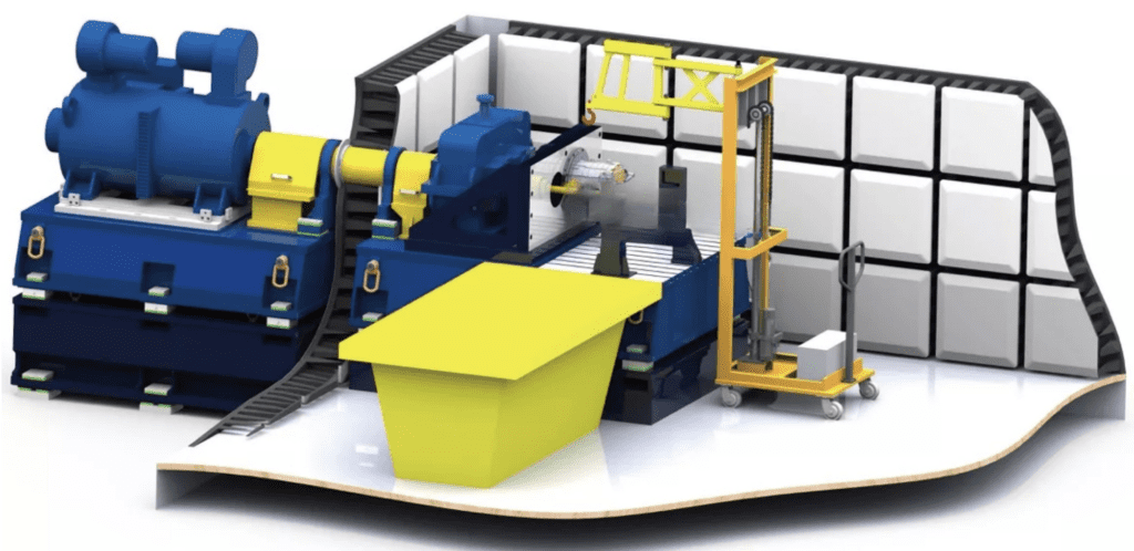
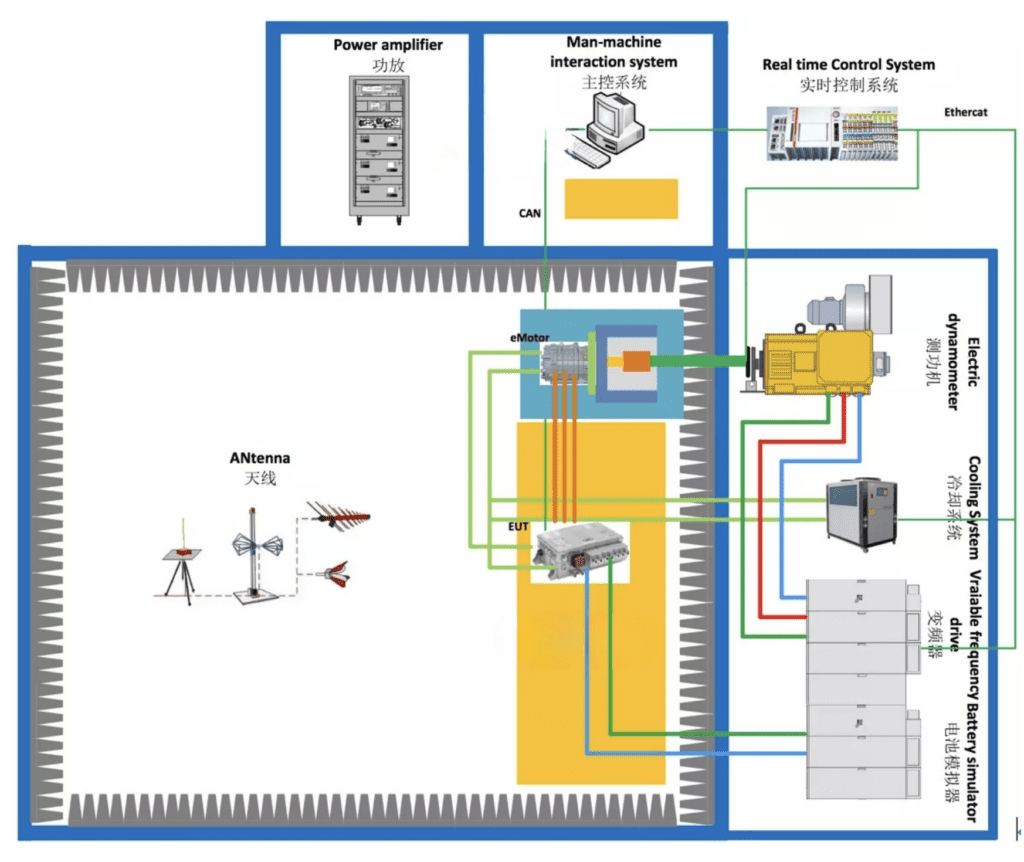
1. System Architecture

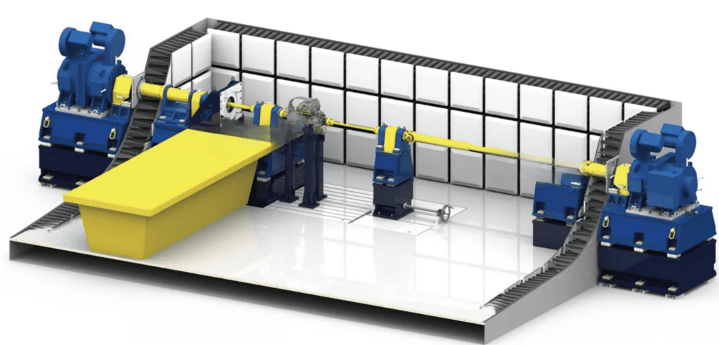
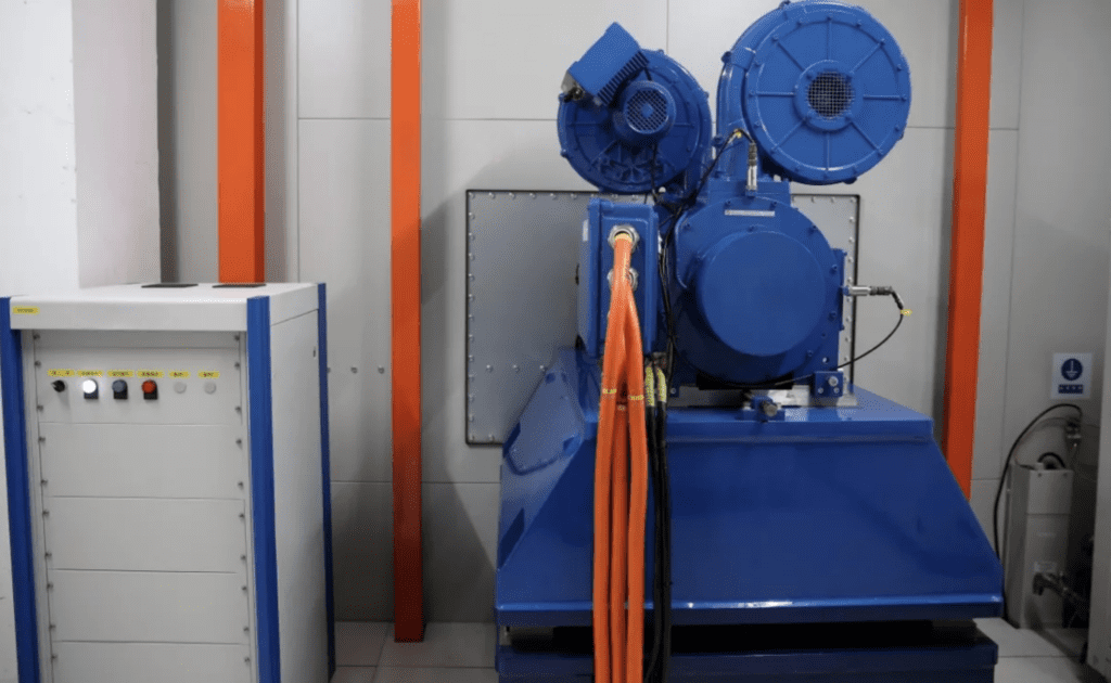
The electric drive EMC/EMI test system is generally composed of electric wave anechoic chamber, dynamometer system and measuring instrument. We generally provide anechoic

chamber and dynamometer system. The anechoic chamber can be a standard CISPR25 anechoic chamber. The dynamometer system needs to be determined according to the

parameters of the product to be tested. The dynamometer system generally includes: a power dynamometer that simulates a load, a through-wall shielding shaft system, an installatio

stand, a frequency converter, a battery simulator, a cooling system, a sensor measurement system, a data acquisition system, and monitoring software.

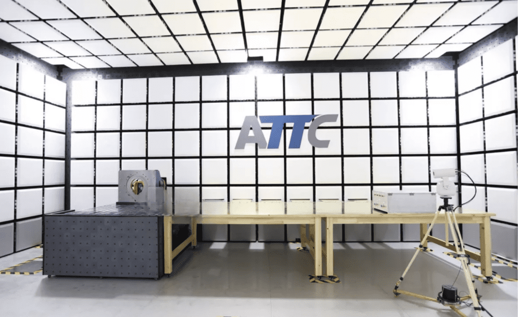
2. Key technical indicators 2.1 Shielding effectiveness-(SE) The shielding effectiveness of the electric drive EMC loading CISPR25 darkroom, control room, and power amplifier room is implemented in accordance with the standard EN50147-1 or the latest GB/T12190 standard (frequency range 10KHz~18GHz). The specific test frequency is determined according to the test frequency of the third-party testing agency, and meets the following indicators:

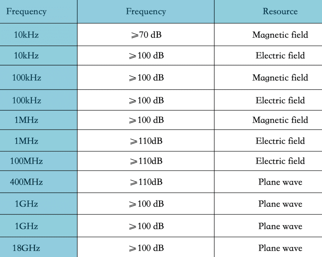
After the installation of all relevant accessories (including the wall shaft) is completed, the electric drive EMC dynamometer works (small non-radiation load can be provided), and the monitoring system, lamps, antenna tower work, and the filter are energized, the shielding effectiveness The level is at least 10dB lower than the Class 5 limit (PK&QP&AV) specified by CISPR25.

2.2 Measurement control accuracy 1) Torque measurement accuracy: ±0.05%FS

2) Pulse resolution of speed sensor: 1024/600pprppr

3) Torque control accuracy: ±1%

4) Speed control accuracy: ±0.01%FS

5) The maximum vibration speed value of the dynamometer (RSM): ≤2mm/s (independent), ≤3.5mm/s (loading)

6) Temperature rise of intermediate bearing seat: ≤35℃

7) The maximum vibration speed value of the intermediate bearing seat (RSM): ≤2mm/s (independent), ≤3.5mm/s (loading)

2.3 Long-line method-(LWM) According to the latest version of CISPR25, the Modelled long wire antenna method (LWM) is adopted in the frequency range of 150kHz~1GHz, and the error of more than 90% of the actual test points is not more than ±6dB compared with the theoretical value of the model. The test area is the motor side and the non-motor side. The test invites an authoritative third-party measurement agency to conduct the test and provide a report.

2.4 Background noise-(ABN) When there is no DUT, monitoring system, lamps, and filters are energized, in the range of 9KHz~6GHz, the test background noise level should be at least lower than the level of the Class 5 limit (PK&QP&AV) specified in the latest version of CISPR25 10dB, which is at least 6dB lower than the GJB151B RE102 limit. This test invites third-party measurement institutions certified by the state to conduct tests and provide reports.

2.5 Air quality After the construction of the radio anechoic chamber is completed, an inspection agency with CNAS and CMA qualification \HuaTest\shall be invited to conduct air quality testing in the darkroom and issue a test for the air quality in the darkroom (including at least formaldehyde, benzene, toluene, dimethylbenzene and TVOC) Report, the test results meet the limit requirements of GB50325-2010 \Indoor Environmental Pollution Control Regulations\and GB/T 18883-2002 \”Indoor Air Quality Standards\”.

2.6 Grounding resistance The anechoic chamber and shielding room are grounded by single-point grounding, and the grounding resistance is designed and constructed by us. The grounding device process uses physical resistance reducers, but does not use chemical resistance reducers. The grounding device is designed to be maintainable. The grounding resistance of dark room and shielded room is less than 1Ω.

3. Implementation standards

1. CISPR16-1-4 \Specifications for Radio Interference and Immunity Test Equipment and Methods Part 1-4: Radio Interference and Immunity Test Equipment Radiated Interference by Auxiliary Equipment\

2. CNAS-CL01-A008 \Instructions for the Application of Testing and Calibration Laboratory Competence Criteria in the Field of Electromagnetic Compatibility Testing\

3. EN50147 \Measurement method of shielding effectiveness of high-performance shielded room\

4. GB/T 12190 \”Measurement Method of Shielding Effectiveness of Electromagnetic Shielding Room\

5. ISO 4589-2 \”Plastics-Determination of burning behaviour by oxygen index Part 2: Ambient-temperature test\

6. GB/T2406 Plastic Combustion Performance Test Method Oxygen Index Method

7. GB 8624 Classification of burning performance of building materials and products;

8. ISO 11452-1/-2/Road vehicles-Test methods for immunity of electronic/electrical components to narrowband radiated electromagnetic energy-Radio anechoic chamber method;

9. CISPR 25 \”Limits and Measurement Methods of Radio Disturbance Characteristics of Vehicles, Ships and Internal Combustion Engines Used to Protect Vehicle-mounted Receivers\

10. MIL-STD-461G REQUIREMENTS FOR THE CONTROL OF ELECTROMAGNETIC INTERFERENCE CHARACTERISTICS OF SUBSYSTEMS AND EQUIPMEN

11.GJB 151BRequirements and Measurements for Electromagnetic Emission and Sensitivity of Military Equipment and Subsystemsl

12.GBT 36282-2018 lElectric Vehicle Drive Motor System Electromagnetic Compatibility Requirements and Test Methods!”

13.GB 50325-2010 “Code for Indoor Environmental Pollution Control of Civil Construction Engineering|”

14.GB/T18883-2002 \Indoor Air Quality\

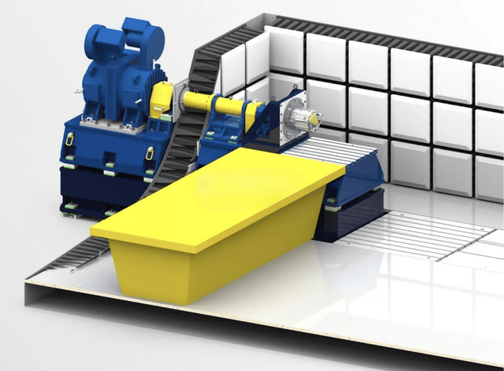
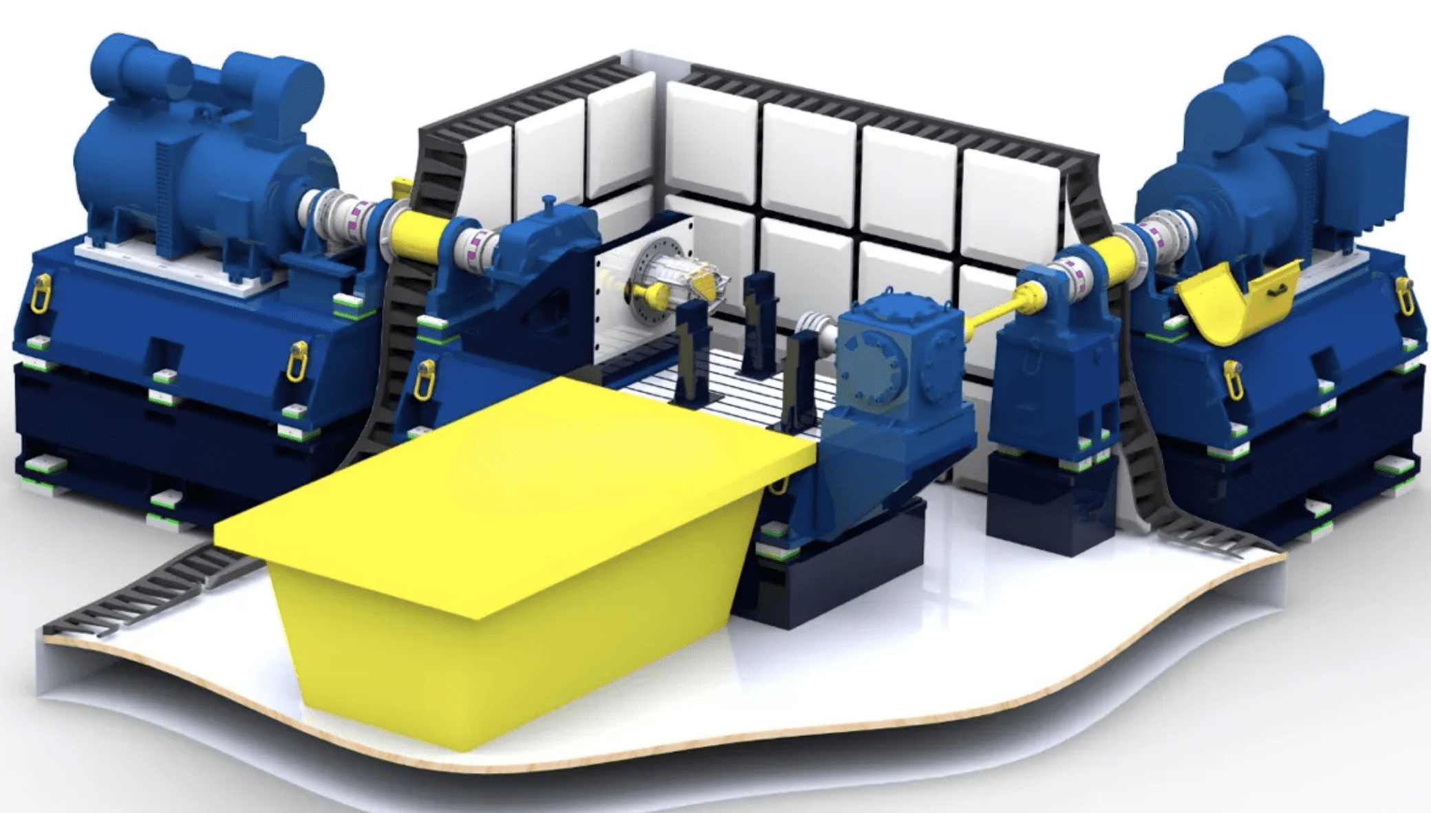
4. Key technology description The key technologies of the EMC test system for motors and drives include: high-speed wall-through shielding shafting, complete electrical isolation system, dark room non-radiation sensor monitoring system, low-noise battery simulator and other systems, real-time monitoring system and other parts.

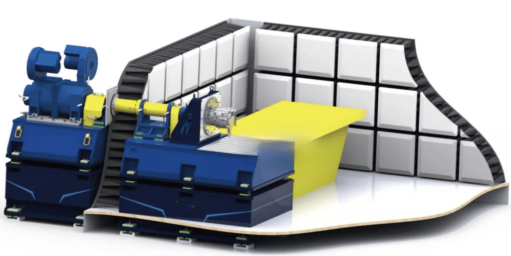
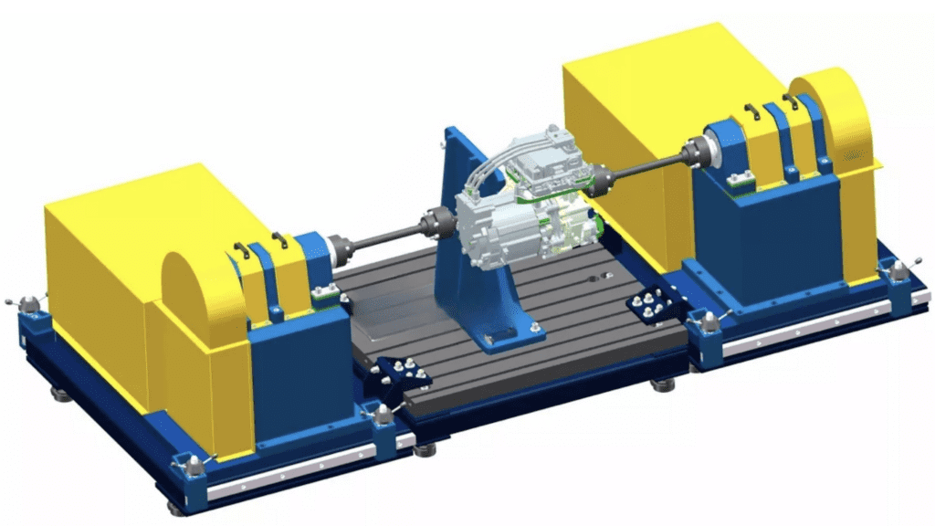
4.1 High-speed through-wall shielding shafting

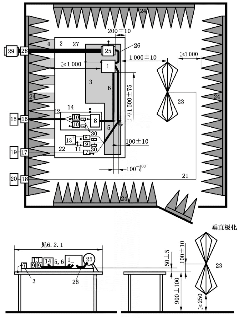
CISPR25 defined test layout

The CISPR25 standard clearly requires that the distance between the controller EUT and the center of the absorbing material is not less than 1m. For the three-in-one electric drive assembly, the distance between the inner side of the controller (near the darkroom side) and the top of the absorbing material is not less than 1m, and the distance between the mounting end of the motor drive assembly and the top of the absorbing material is not less than 1m. In order to meet this requirement, the length of the shaft system is longer, and at the same time, it needs to meet the requirement of less vibration at high speed. The current foreign solution is to use carbon fiber shaft or glass fiber shaft, the test conditions require that the length of the shaft must be greater than 1.6 meters (international standards stipulate that the distance between the end face of the motor under test and the top of the anechoic chamber absorbing material is not less than 1m, considering the absorbing material Thickness, ferrite thickness, and shield thickness, while also taking into account the error during installation). Although these two non-metallic shafts are excellent materials that are non-conductive and non-magnetic, because the electric drive system of new energy vehicles has entered the stage of high-speed and high-torque, the absolute elastic modulus of glass fiber or carbon fiber shafts is not suitable for high-speed and high-torque testing. Scenes.

The high-speed through-wall shielding shaft designed by our company has the following characteristics:

  1. Adopt high-precision and low-inertia rigid shaft, while taking into account the characteristics of high speed and large torque.
  2. As a part of the anechoic chamber, the rotating shaft has good conductivity, fundamentally shields external electromagnetic radiation, achieves an excellent shielding effect, and reduces background noise in the darkroom.
  3. Through the detachable shielding cover, the test motor can be completely shielded, and the electromagnetic compatibility characteristics of the drive axle can be tested independently.

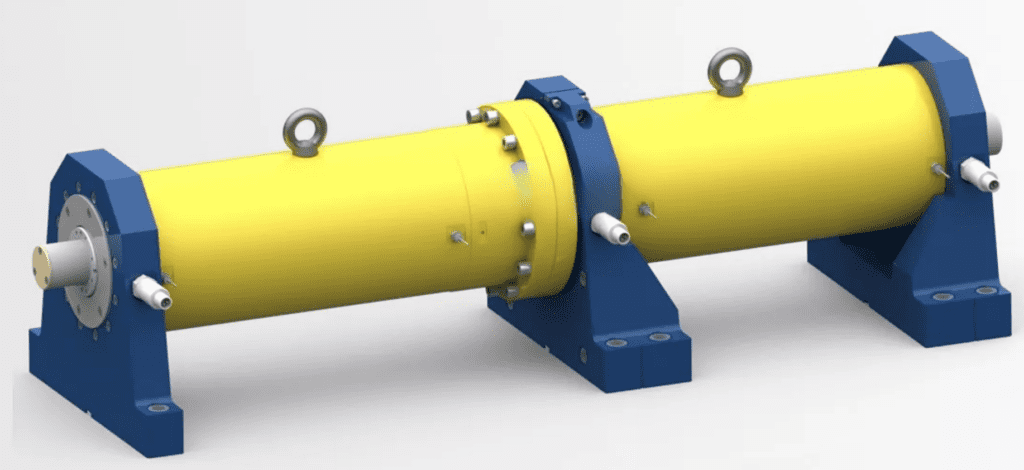
In order to meet the high-speed, large-torque and shielding requirements at the same time, the system adopts a high-precision long-axis system.

  1. The vibration speed in the full speed range is less than 3.5mm/s.
  2. The shaft system adopts a multi-point support structure, which is convenient for centering the base in the dark room and the coaxiality is better than 0.02mm.
  3. The shaft system has a fully dynamic balance structure, and the dynamic balance accuracy reaches G1.
  4. The first-order critical speed of the shaft system is higher than the maximum speed of the system.

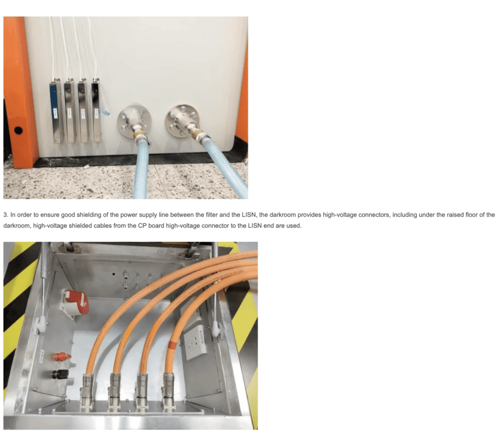
4.2 Completely electrically isolated system

In order to prevent electromagnetic waves and charges from being conducted outside the anechoic chamber to the anechoic chamber, in addition to special electromagnetic shielding methods, the dynamometer must be completely electrically isolated. Electric drive motors or powertrains need to meet single-point grounding requirements.

  1. The dynamometer and the shielded shaft adopt high-speed insulation coupling.
  2. The dynamometer is completely electrically isolated from the base.
  3. The high-speed shielded shaft and the tested electric drive motor shaft adopt high-speed insulation coupling.
  4. The installation base in the anechoic chamber is completely electrically isolated from the anechoic chamber.
  5. The anechoic chamber is designed with a removable complete shielding cover, which can completely shield the motor and test the EUT of the controller individually.

4.3 Non-radiation sensor monitoring system in dark room

The electric drive system and shaft system under test in the anechoic chamber are all designed with vibration and temperature monitoring sensors. The sensors need to be collected by a high-speed data acquisition system and transmitted to the monitoring software for signal analysis and processing. The data acquisition system is placed in the anechoic chamber. Due to its own radiation, the background noise of the anechoic chamber will be affected, and low noise processing is required.

Our company has made the following designs for the data acquisition system in the anechoic chamber:

  1. The power supply of the data acquisition system is filtered by a 24V filter to eliminate the power interference entering the electric wave dark room.
  2. The signal transmission design of the data acquisition system. Real-time Ethernet optical fiber converter, through optical fiber and optical fiber waveguide installed on the wall of the anechoic chamber, transmits the signal to the anechoic chamber, and then converts it into a digital signal through an inverse converter, and enters the upper position In the machine.
  3. The data acquisition system is installed in a shielded box. The shielded box is designed with ventilation waveguides to ensure heat dissipation and at the same time ensure that the electromagnetic waves in the box will not be transmitted to the dark room.
  4. The sensor cable adopts a special shielded cable, which connects the sensor and the shielded box as a whole.

4.4 Low noise battery simulator

The battery simulator supplies power to the motor controller under test, can simulate the battery, and can also perform battery pack charge and discharge tests.

1. Output voltage:

  • Maximum output voltage (Unom): 1200V
  • Output voltage range: 20V~ Unom adjustable, setting resolution: 0.1V
  • Repeatability: ≤0.1% Unom
  • Voltage rise time (10% to 90% Unom): <5ms (resistive load)
  • Load change (10% to 90%) control time: ≤1ms (resistive load)
  • Residual ripple: ≤0.2% Unom effective value (frequency DC-1MHz)

2. Output current:

  • Maximum output current (Inom): 800A
  • Output current range: 0~ Inom adjustable, setting resolution: 0.1A
  • Repeatability: ≤0.1% Inom
  • Current rise time (10% to 90% Inom): <1ms (resistive load)
  • Load change (10% to 90%) control time: ≤1ms (resistive load)
  • Temperature coefficient: ≤0.01% Inom/K
  • Residual ripple: ≤0.2% Inom effective value (frequency DC-1MHz)
  1. Output power: ‡350kW
  2. Output efficiency: >90%
  3. Output accuracy: 0.1%
  4. Internal resistance:
  • Setting range: 0~ 5W (adjustment resolution 0.1mW)
  • Battery mode: by adjusting internal resistance

The parameters of the battery simulator can be customized according to actual needs.

4.5 Real-time monitoring system

The monitoring system adopts embedded real-time controller control, real-time Ethernet communication, and all communication cables entering the control room are transmitted through optical fibers.

  1. Real-time monitoring of the front and rear bearings and temperature of the dynamometer, real-time monitoring of the current and voltage of the dynamometer, and real-time monitoring of the speed and torque of the dynamometer.
  2. Shield the real-time monitoring of the vibration of the long axis.
  3. Real-time monitoring of the vibration of the motor under test.
  4. The electronic control system has protection functions such as short circuit, leakage, power failure, overcurrent, and overvoltage.
  5. The system software has a safety detection function. When the monitoring value exceeds the threshold, it will immediately alarm. The system has three levels of protection.
  6. The dark room adopts a non-electromagnetic radiation photoelectric isolation data acquisition system, which collects vibration sensor and temperature sensor signals in real time, and transmits them to the control room through optical fiber for real-time monitoring.
  7. Emergency stop buttons are designed near the test table in the dark room, in the control room, near the dynamometer, etc..
erreur: Le contenu est protégé !!