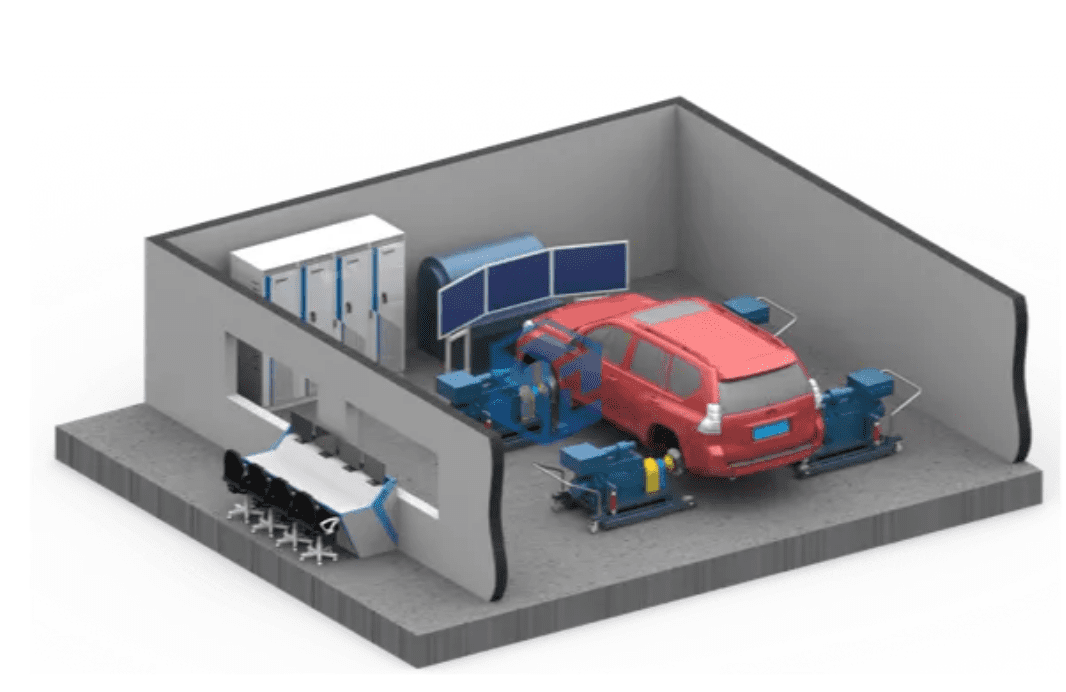
The dynamometer can perform speed and torque control to simulate road load. Load simulation methods include: constant torque control, calculated road spectrum simulation, actual road spectrum import, and user-defined load spectrum. The power analyzer measures the current, voltage and power of each energy consumption unit of the tested vehicle, analyzes the energy flow of the vehicle under different operating conditions, and draws the energy spectrum of the entire vehicle. The dynamometer adopts a low-inertia dynamometer, which has extremely high dynamic characteristics and can simulate rapidly changing working conditions and simulate different road models. By integrating into the traffic scene simulation system, real vehicle actions under different road conditions can be truly reproduced, including the driver’s operating comfort. The system can also be transformed into a powertrain test system, and the battery simulator can be connected to the powertrain drive to test the powertrain.
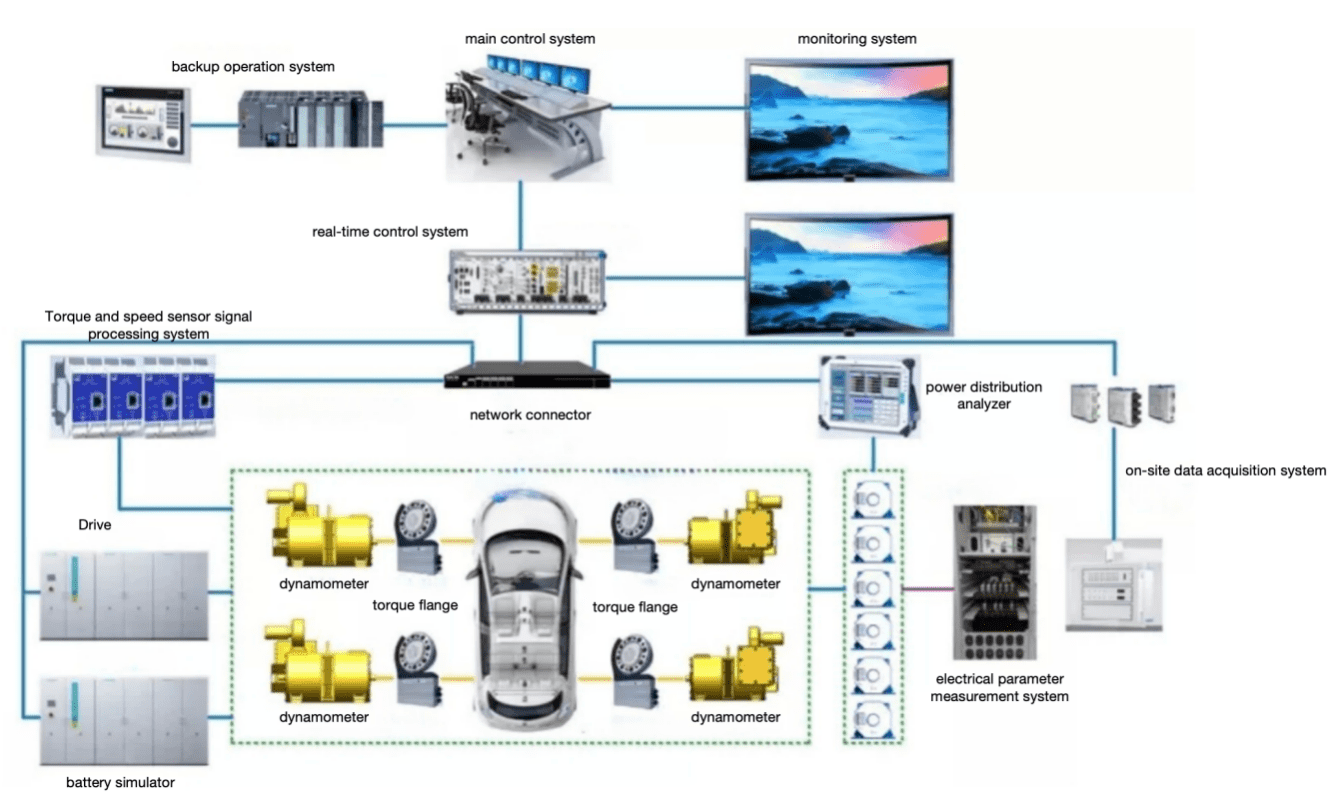
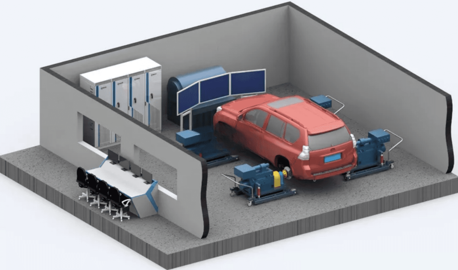
The shaft coupling dynamometer adopts a flexible design. Each dynamometer adopts a movable mode. The dynamometer and the vehicle hub adopt a quick connection structure, so that the user can quickly and quickly complete the connection between the vehicle and the dynamometer. The dynamometer tray bracket is supported by universal wheels, which can be moved conveniently, and at the same time, it can also simulate the actual steering function.
Pure electric vehicle driving range test will use Chinese working conditions GB/T 18386 \”Electric Vehicle Energy Consumption and Driving Range Test Method\” standard. It is determined that Chinese working conditions will replace European NEDC working conditions as the test conditions, and will be introduced High and low temperature test procedures.
In the energy transmission path, there are lossy systems and components, and the corresponding energy consumption form. The quantified energy consumption distribution for energy consumption systems and components.
Data from EPA:

Vehicle energy flow test:
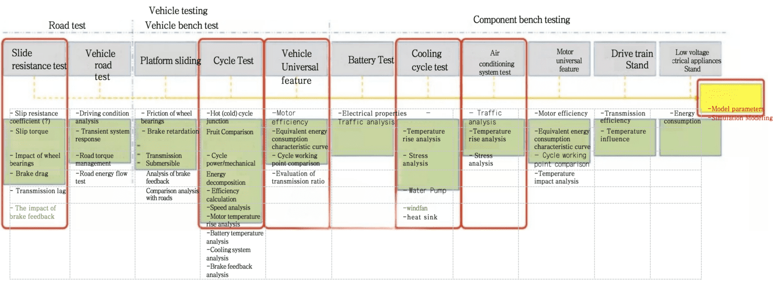
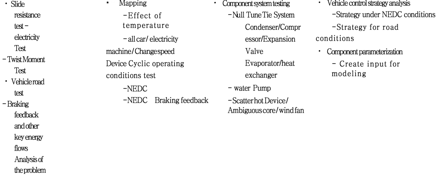
After the vehicle has undergone the loss calibration and coasting test, the formal test is carried out. At this time, the simulated load of the dynamometer is similar to the road load of the vehicle.
At the same time, the user needs to consider that the friction loss will change with the change of the ambient temperature. Therefore, it is necessary to warm up the device before friction calibration or test and maintain its temperature until the end of the test.
When the vehicle loss calibration is completed, the page will automatically update and display the maximum calibration speed. The calibration of friction loss can be analogized to the calibration of vehicle loss. The maximum calibration speed displayed is the lower of the friction calibration speed and the vehicle loss calibration speed.
The basic inertia calibration is used to calibrate the basic inertia of the test bench, including: the total moment of inertia of each transmission system such as the drum, drive shaft, and motor. The basic inertia calibration is a necessary condition for the correct operation of the test bench.
5.5 Glide test

Für Fragen oder Unterstützung, Bitte kontaktieren Sie uns per E-Mail unter info@econotests.com.
Wir sind bestrebt, zeitnah zu reagieren.
Brauche sofortige Hilfe? Rufen Sie uns an +86 156 1877 0706.
Unser Team steht Ihnen gerne zur Verfügung.
Wir heißen Sie herzlich willkommen, unser Büro unter zu besuchen 3F, Gebäude 2, Nr. 511 Xiaowan Road, Fengxian, Shanghai, China.
Let's discuss your needs in person.

© 2024 Shanghai EconoTechnology Co., Ltd. Alle Rechte vorbehalten.
Förderung von Innovationen durch zuverlässige Testlösungen.